Sensing circuit of capacitance type touch panel

A capacitive touch and sensing circuit technology, applied in electrical digital data processing, input/output process of data processing, instruments, etc., can solve the problem that the difference in voltage change is too small and the circuit cannot calculate the position of the contact point based on it , the difference in the amount of induced charge is too small, etc.

Active Publication Date: 2011-06-22
ORISE TECH CO LTD
View PDF1 Cites 0 Cited by
  • Summary
  • Abstract
  • Description
  • Claims
  • Application Information

AI Technical Summary

Problems solved by technology

[0012] However, when the mutual capacitance Cs on the contact point changes very little, the difference between the induced charge amount and the induced charge amount of other mutual capacitances is too small, which will cause the voltage change amount generated by the sensing circuit corresponding to the contact point to be different from that of other sensing circuits. The difference in the voltage change of the circuit is too small, so that the subsequent circuit cannot calculate the position of the contact point

Method used


Image

  • Sensing circuit of capacitance type touch panel
  • Sensing circuit of capacitance type touch panel
  • Sensing circuit of capacitance type touch panel

Examples


Embodiment Construction

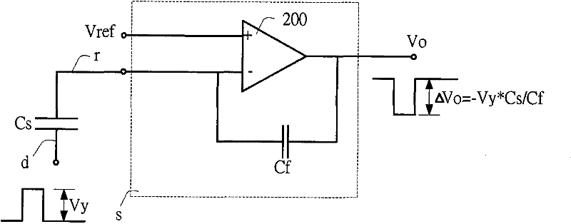
[0033] Please refer to Figure 4A and Figure 4B , which shows the first embodiment of the sensing circuit and its control signal of the present invention. The sensing circuit s includes: an operational amplifier 400, a feedback capacitor Cf, and four switch circuits sw1˜sw4. Moreover, the driving signal P can generate induced charges in the mutual capacitance Cs through the driving electrode d, and transmit to the input terminal of the sensing circuit s through the receiving electrode r.

[0034] Wherein, the input end of the sensing circuit s is connected to the first end of the first switch sw1 (controlled by the first control signal ctr1) and the first end of the second switch sw2 (controlled by the second control signal ctr2), and the first end of the first switch sw1 The two terminals are connected to the third switch sw3 (controlled by the third control signal ctr3) and the first terminal of the feedback capacitor Cf; the negative input terminal (-) of the operational...


PUM


Abstract

The invention relates to a sensing circuit of capacitance type touch panel, comprising a first switch, a second switch, a third switch, a feedback capacitor, a fourth switch and a computing amplifier; the first switch is provided with a first end to be connected to a receiving electrode of the capacitance type touch panel; the second switch is provided with a first end to be connected to the receiving electrode of the capacitance type touch panel; the third switch is provided with a first end to be connected to a second end of the first switch; the feedback capacitor is provided with a first end to be connected to a second end of the first switch; the fourth switch is provided with a first end to be connected to a second end of the feedback capacitor; the computing amplifier is provided with a positive input end to be connected to a grounding end, a negative input end to be connected to the first end of the fourth switch, and an output end to be connected to the second ends of the second switch, the third switch and the fourth switch, driving signals can be used for controlling the act sequence of the above switches in driving period, so that the computing amplifier can generate output voltage. The invention can cause SNR to increase, and vastly improve sensing capability of touch panel.

Description

technical field [0001] The present invention relates to a sensing circuit of a touch panel, and in particular to a sensing circuit of a capacitive touch panel. Background technique [0002] Please refer to figure 1 , which is a schematic diagram of a known capacitive touch panel system. The capacitive touch panel system includes: driving units u1˜u6, sensing circuits s1˜s6, and a touch panel. Wherein, the touch panel includes non-contact driving electrodes d1-d6 and receiving electrodes r1-r6, and each driving electrode d1-d6 is connected to the output terminal of the corresponding driving unit u1-u6 , each receiving electrode r1-r6 is connected to the corresponding input terminal of the sensing circuit s1-s6. Furthermore, the driving electrodes d1-d6 and the receiving electrodes r1-r6 which are not in contact with each other will generate mutual capacitances (mutual capacitance) Cs11-Cs66. certainly, figure 1 The capacitive touch panel only takes six driving electrodes...

Claims


Application Information

Patent Timeline
Patent Type & Authority Patents(China)
IPC IPC(8): G06F3/044
Inventor 王信濠黄彦霖
Owner ORISE TECH CO LTD
Why Eureka
Try Eureka