Torque sensor

A technology of torque sensor and Hall sensor, which is applied in the direction of force/torque/power measuring instrument, instrument, torque measurement, etc., can solve the problem that the torque sensor is difficult to cope with the miniaturized current demand, so as to improve the measurement performance and simplify the assembly process, the effect of improving sensing capabilities

Active Publication Date: 2020-04-10
LG INNOTEK CO LTD
View PDF14 Cites 0 Cited by
  • Summary
  • Abstract
  • Description
  • Claims
  • Application Information

AI Technical Summary

Problems solved by technology

[0009] Therefore, the torque sensor has a problem that it is difficult to cope with the current demand requiring miniaturization

Method used


Image

  • Torque sensor
  • Torque sensor
  • Torque sensor

Examples


no. 1 example

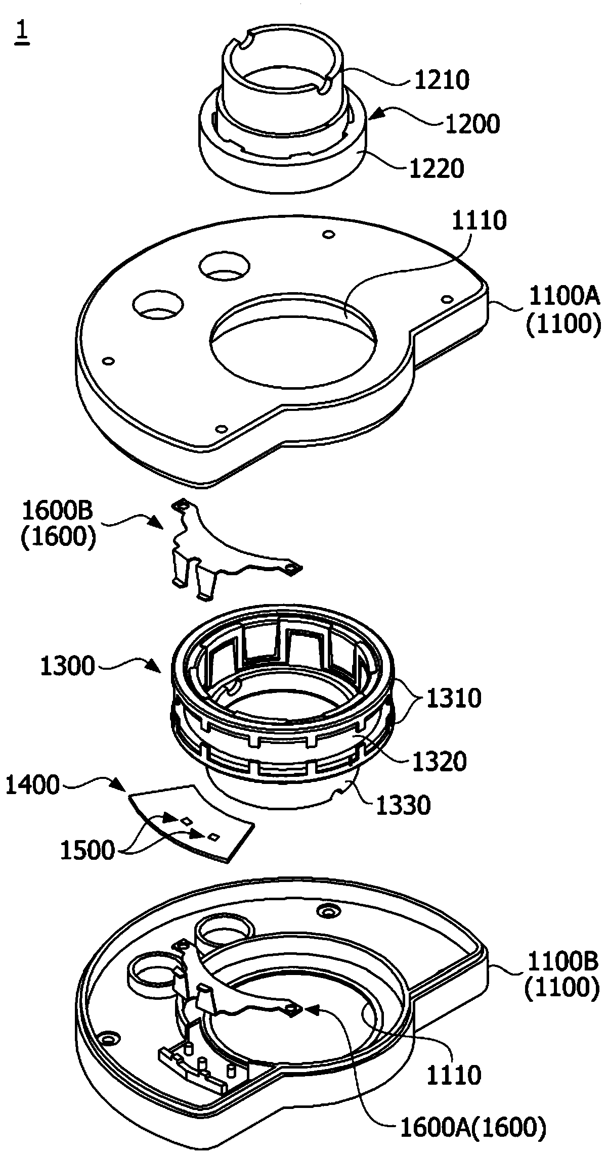
[0069] figure 1 is a view showing the torque sensor according to the first embodiment.

[0070] refer to figure 1 , the torque sensor 1 according to the first embodiment may include a housing 1100 , a rotor 1200 , a stator 1300 , a circuit board 1400 , a Hall sensor 1500 (Hall Integrated Circuit (IC)), and a collector 1600 .

[0071] The case 1100 may include upper and lower parts coupled to each other. In addition, the housing 1100 includes a hole 1110 provided at the center thereof. The stator 1300 is located within the bore 1110 . The circuit board 1400 and the collector 1600 may be disposed within the case 1100 .

[0072] The rotor 1200 is provided inside the stator 1300 . The rotor 1200 is connected to the input shaft of the steering shaft. Here, the input shaft may be a steering shaft connected to a steering wheel of the vehicle. The rotor 1200 may include a yoke 1210 having a cylindrical shape and a magnet 1220 disposed around the yoke 1210 . The input shaft is ...

no. 2 example

[0102] The torque sensor 2 according to the second embodiment may be provided between an input shaft (not shown) and an output shaft (not shown) of the steering shaft. Here, the torque sensor 2 may be referred to as a sensor assembly.

[0103] Figure 8 is an exploded perspective view showing the torque sensor according to the second embodiment, and Figure 9 is a side view of the rotor, stator, pinion, collector and circuit board of the torque sensor according to the second embodiment. here, Figure 8 and Figure 9 The shown x direction represents the axial direction, and the y direction represents the radial direction. In addition, the axial direction is perpendicular to the radial direction.

[0104] refer to Figure 8 and Figure 9 , The torque sensor 2 according to the second embodiment may include a housing 2100 , a rotor 2200 connected to an input shaft, a stator 2300 or 2300 a connected to an output shaft, a pinion 2400 , a collector 2500 , and a circuit board 2...


PUM


Abstract

An embodiment can provide a torque sensor comprising: a housing; a rotor that is arranged inside the housing; a stator that is arranged on an outer side of the rotor; a circuit board that is arrangedin the housing; a Hall-effect sensor that is arranged on the circuit board; and a collector that is arranged adjacent to the Hall-effect sensor, wherein the collector includes a body portion and an extension portion extending from the body portion, the body portion is arranged to be spaced apart from the housing, and the extension portion is directly in contact with the housing.

Description

technical field [0001] Embodiments relate to a torque sensor. Background technique [0002] Electric Power Steering (hereinafter referred to as "EPS") allows an Electronic Control Unit (ECU) to drive an electric motor according to driving conditions to ensure steering stability and quickly provide restoring force, enabling the driver to drive stably. [0003] The EPS includes a torque sensor that measures the torque of the steering shaft to provide the proper torque. The steering shaft may include: an input shaft connected to a steering wheel; an output shaft connected to a power transmission system on a wheel side; and a torsion bar connecting the input shaft to the output shaft. [0004] The torque sensor measures the torque applied to the steering shaft by measuring how much the torsion bar is twisted. Such a torque sensor may include a rotor, a stator and a collector. The collector measures the magnetization of the stator. [0005] The collector is made of metal mate...

Claims


Application Information

Patent Timeline
Patent Type & Authority Applications(China)
IPC IPC(8): G01L19/14G01L3/14G01L5/22B62D6/10B62D15/02
CPCB62D6/10G01L3/104G01L5/221B62D15/02G01L3/1428G01L19/147G01L19/148
Inventor 李树炯禹明喆
Owner LG INNOTEK CO LTD
Why Eureka
Try Eureka