Micromirror device including dielectrophoresis liquid

A dielectrophoretic and liquid technology, applied in the field of micromirror devices, can solve the problem of reducing the resolution of the display

Inactive Publication Date: 2004-09-22
HEWLETT PACKARD DEV CO LP
View PDF1 Cites 0 Cited by
  • Summary
  • Abstract
  • Description
  • Claims
  • Application Information

AI Technical Summary

Problems solved by technology

However, conventional micromirror devices must be of sufficient size to allow rotation of the mirror relative to the support structure
However, increasing the size of the micromirror devices reduces the resolution of the display because there are fewer micromirror devices on a given area

Method used


Image

  • Micromirror device including dielectrophoresis liquid
  • Micromirror device including dielectrophoresis liquid
  • Micromirror device including dielectrophoresis liquid

Examples


example

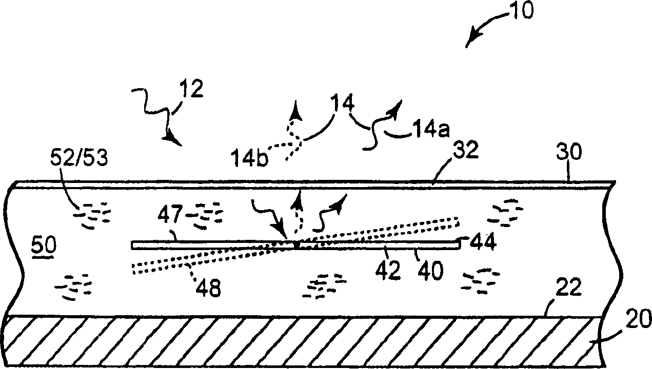
[0086] In a representative embodiment, various liquids as shown in Table 1 are filled in the experimental micromirror device. As shown, the dielectric constant of the liquid is related to the movement of the mirror, and a liquid with a dielectric constant of less than 20 is favorable for the movement of the mirror. In addition, for liquids with a dielectric constant less than 20, the amount of motion is related to the dipole moment, and mirrors including liquids with higher dipole moments require less excitation energy to produce mirror motion. For example, in one embodiment, the voltage used to energize the mirror is about 13.8 volts when using hexane and about 10.2 volts when using diphenyl ether.

[0087] example

[0088] N * Indicates undesirable outgassing


PUM


Abstract

A micro-mirror device includes a substrate (20) having a surface (22), and a plate (30) spaced from and oriented substantially parallel to the surface of the substrate such that the plate and the surface of the substrate define a cavity (50) therebetween. A dielectrophoretic liquid (53) capable of movement when an electrical signal is applied to the micro-mirror device is disposed in the cavity, and a reflective element is interposed between the surface of the substrate and the plate such that the reflective element (42) is adapted to move between a first position and at least one second position.

Description

[0001] Cross References to Related Applications [0002] This application is a continuation-in-part of co-pending US Patent Application No. 10 / 136719, filed April 30, 2002, which is assigned to the assignee of the present invention and is incorporated herein by reference. technical field [0003] The present invention relates generally to microactuators, and more particularly to micromirror devices comprising dielectrophoretic liquids. Background technique [0004] Microactuators have been formed on insulators or other substrates by using microelectronic techniques such as photolithography, vapor deposition, and etching. Such microactuators are commonly referred to as microelectromechanical systems (MEMS) devices. Examples of microactuators include micromirror devices. Micromirror devices can function as light modulators for amplitude and / or phase modulation of incident light. One application of micromirror devices is in display systems. In this case, a plurality of micr...

Claims


Application Information

Patent Timeline
Patent Type & Authority Applications(China)
IPC IPC(8): B81B3/00G02B5/08G02B26/02G02B26/08
CPCY10S359/904B81B7/04G02B26/0841G02B26/004B81B2203/0109B81B2201/042
Inventor P·F·雷波亚R·W·施里夫T·E·麦克马洪
Owner HEWLETT PACKARD DEV CO LP
Why Eureka
Try Eureka