Barning type power tool with preventer for avoiding mechanical parts overheat in tools

A technology of power tools and combustion chambers, which is applied in the field of combustion-type fastener driving tools, and can solve the problems of not being able to provide small tools

Inactive Publication Date: 2004-09-29
KOKI HLDG CO LTD
View PDF3 Cites 19 Cited by
  • Summary
  • Abstract
  • Description
  • Claims
  • Application Information

AI Technical Summary

Problems solved by technology

Therefore, small tools cannot be provided

Method used


Image

  • Barning type power tool with preventer for avoiding mechanical parts overheat in tools
  • Barning type power tool with preventer for avoiding mechanical parts overheat in tools
  • Barning type power tool with preventer for avoiding mechanical parts overheat in tools

Examples


Embodiment Construction

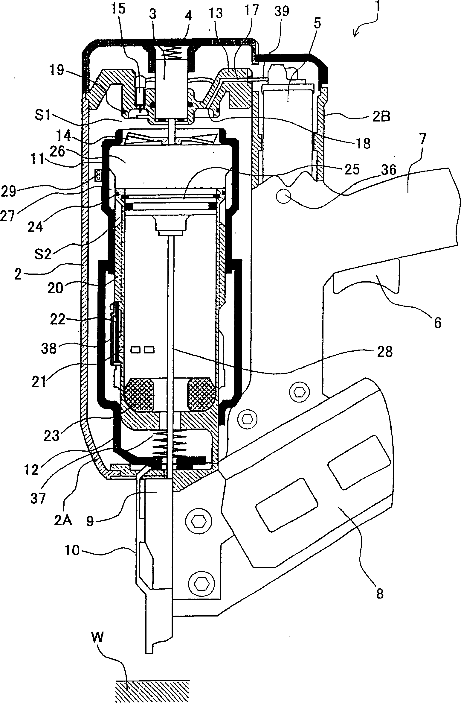
[0035] The following will refer to figure 1 to 3(b) specifically describe the combustion type power tool according to the first embodiment of the present invention. This embodiment is suitable for combustion type nail drivers. The combustion type nail driver 1 has a housing 2 constituting an outer frame, and includes a main housing 2A and a canister housing 2B juxtaposed with the main housing 2A. The main housing 2A has a top end portion provided with a top end cover 4 in which an air intake port is formed, and has a bottom end portion in which an air discharge port (not shown) is formed.

[0036] A gas tank 5 including combustible gas therein is detachably provided in the tank case 2B. A handle 7 with a trigger switch 6 extends from the tank housing 2B. A battery for driving the motor 3 and a glow plug 15 which will be described later are accommodated in the handle 7 . A storage case 8 and a tail cap 9 are provided at the bottom of the main case 2A and the tank case 2B. ...


PUM


Abstract

A combustion type power tool capable of avoiding damage to seal members and a housing to prolong a service life, and capable of enhancing operability and workability. Temperature elevation of a combustion chamber frame due to combustion of a mixture of combustible gas and air is detected by a temperature sensor disposed in a housing. If the detected temperature exceeds a preset temperature, ignition of an ignition plug is prohibited by a prohibiting unit in spite of ON operation of a trigger switch. In this state, alarming is performed by a display to notify the user of inoperable sate of the tool. Similar control can be made when the temperature sensor is disposed at a cylinder, an exhaust cover and the housing.

Description

technical field [0001] The present invention relates to a combustion type power tool, and more particularly, to a combustion type fastener driving tool in which liquefied gas is injected from a gas tank into a combustion chamber, mixed with the gas and ignited to drive a piston, Power is thus generated to drive a nail or other similar device. Background technique [0002] Traditional combustion-type driving tools usually include housings, handles, trigger switches, top end covers, combustion chamber frames, push rods, cylinders, pistons, drive blades, electric motors, fans, gas tanks, ignition plugs, waste gas check valves, exhaust covers , storage case and tail cap. The end cover closes one end of the casing and forms a combustion gas passage. A handle is secured to the housing and provided with a trigger switch. The combustion chamber frame moves longitudinally within the casing. The combustor frame is urged away from the top end cap by a spring, and one end of the com...

Claims


Application Information

Patent Timeline
Patent Type & Authority Applications(China)
IPC IPC(8): B25C1/08
CPCB25C1/08
Inventor 大森康希佐佐木康雄藤泽治久
Owner KOKI HLDG CO LTD
Why Eureka
Try Eureka