

Adsorbing nozzle and mounting device of part using the same
A technology of adsorption nozzles and adsorption holes, which is applied to electrical components, electrical components, conveyor objects, etc., can solve problems such as cost increase, and achieve the effect of increasing sliding resistance and reducing buffer function.
- Summary
- Abstract
- Description
- Claims
- Application Information
AI Technical Summary
Problems solved by technology
Method used
Image

Examples
Embodiment Construction
[0027] Hereinafter, specific embodiments of the present invention will be described in detail with reference to the accompanying drawings.
[0028] (implementation form 1)
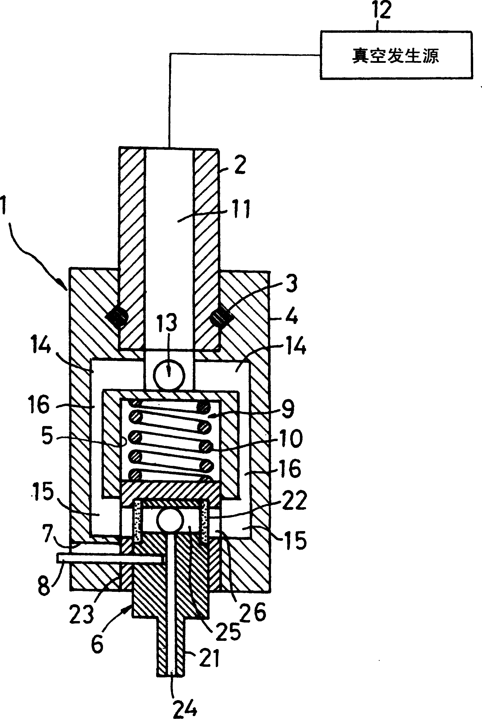
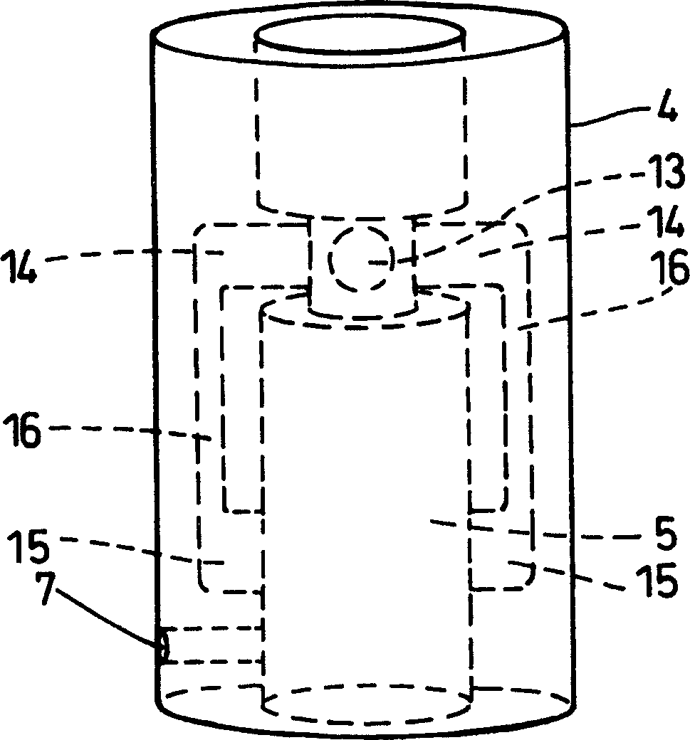
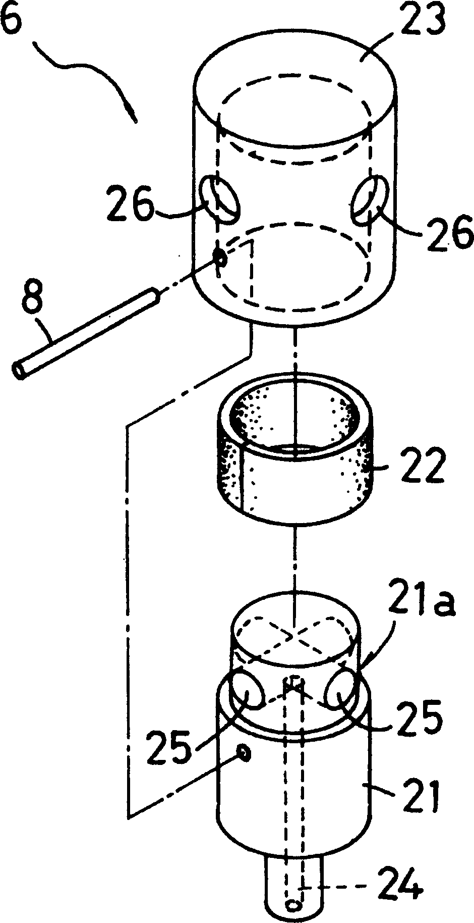
[0029] figure 1 It is a longitudinal sectional front view of a suction nozzle according to an embodiment of the present invention, figure 2 yes figure 1 The three-dimensional view of the appearance of the muzzle 4, image 3 yes figure 1 An exploded perspective view of the front end nozzle 6 of .
[0030] The suction nozzle 1 of this embodiment is detachably mounted on the lower end of the support rod 2 protruding from the mounting machine. This suction nozzle 1 has: a mouth cover 4 that is inserted from the outside, mounted on the lower end of the support rod 2, and held in position by an O-ring 3, and a mouth support hole that is inserted into the mouth insertion portion formed at the front end of the mouth cover 4. The front end suction nozzle 6 supported in 5.
[0031] On the lower peripheral...
PUM
 Abstract
Description
Claims
Application Information