Right-angle gear speed reducer

A gear reduction, orthogonal shaft technology, applied in the direction of gear transmission, belt/chain/gear, coupling, etc., can solve the problems of fretting wear, hindering the improvement of the durability of the reducer, and easily reducing the durability of shock loads. , to achieve the effect of improving impact resistance, sufficient durability, and preventing deterioration

Inactive Publication Date: 2004-10-06
SUMITOMO HEAVY IND LTD
View PDF1 Cites 22 Cited by
  • Summary
  • Abstract
  • Description
  • Claims
  • Application Information

AI Technical Summary

Problems solved by technology

[0004] However, in the use of such conventionally known wedge-coupled speed reducers, in the case of such an application in which the start and stop of the speed reducer are frequently repeated, the wedge joint is subjected to intermittent impact loads. The wedge joint that transmits power is prone to the so-called "fretting" fretting problem, which is the main factor that hinders the durability of the reducer
In particular, in the orthogonal shaft gear reducer, the orthogonal gear set generally adopts a cantilever structure, so there is a problem that the durability against impact loads tends to decrease.

Method used


Image

  • Right-angle gear speed reducer
  • Right-angle gear speed reducer

Examples


Embodiment Construction

[0012] Embodiments of the present invention will be described below with reference to the drawings.

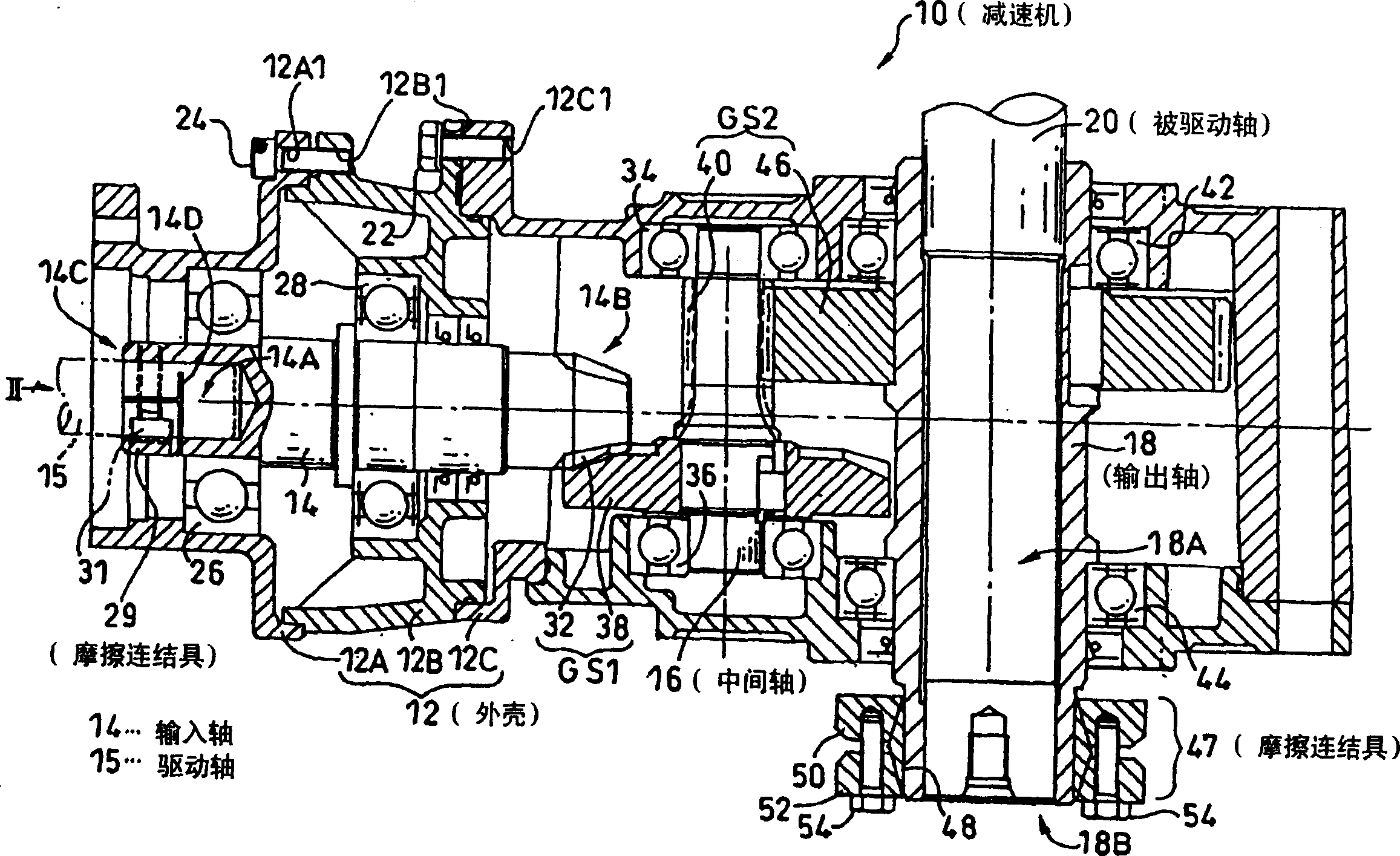
[0013] figure 1 It is a side sectional view of the orthogonal axis gear reducer 10 according to the embodiment of the present invention.

[0014] This orthogonal axis gear reducer 10 has a casing 12, and in the casing 12, an input shaft 14 arranged in the transverse direction in the drawing and an intermediate shaft 16 arranged in a direction perpendicular to the input shaft 14 are respectively provided. , and an output shaft 18 disposed parallel to the intermediate shaft 16 .

[0015] The housing 12 is composed of three first, second, and third housings 12A, 12B, and 12C. Bolt holes 12A1, 12B1, and 12C1 are respectively formed in the first to third casings 12A to 12C, and the first to third casings 12A to 12C can be connected to each other by a plurality of bolts 22, 24 (only a part is shown in the figure). combined.

[0016] The input shaft 14 arranged in the housing 12 ...


PUM


Abstract

Provided is an orthogonal gear reducer in which sufficient durability can be obtained even in use such that starting and stopping are frequently repeated, and the shock resistance of the whole gear reducer can be increased. In the orthogonal axis gear reducer, a one-stage parallel shaft gear set (GS0) is arranged at a rear stage of a hypoid gear set (GS1), and friction fasteners (29) and (47) for fastening a shaft and another shaft and enabling the transmission of power by a frictional force between the shafts are provided at ends of an input shaft (14) and an output shaft (18). Both the input shaft (14) and a driving shaft (15) of the drive device, and the output shaft (18) and a driven shaft (20) of the driven device can be fastened with the friction fasteners (29) and (47).

Description

technical field [0001] The present invention relates to an orthogonal shaft gear reducer having an orthogonal gear set comprising: an input shaft supported by a cantilever having an orthogonal pinion formed at the front end, and an input shaft meshing with the orthogonal pinion Orthogonal gears. Background technique [0002] The well-known orthogonal shaft gear reducer in the past has an orthogonal gear set including: an input shaft supported by a cantilever with an orthogonal pinion formed at the front end; The orthogonal gear decelerates the rotation input from the driving device to the input shaft, and transmits the decelerated rotation to the driven device through the output shaft. However, there are generally many kinds of mechanical components that connect shafts and shafts. In the field of reducers including the above-mentioned orthogonal shaft gear reducers, the widely used method is to use wedges to connect the input shaft and the drive shaft of the drive device, a...

Claims


Application Information

Patent Timeline
Patent Type & Authority Applications(China)
IPC IPC(8): F16H1/20F16D1/06F16H1/02F16H1/12F16H1/28
CPCF16H1/145
Inventor 山本章
Owner SUMITOMO HEAVY IND LTD
Why Eureka
Try Eureka