Structure for reducing resonance noise of external shell of fan for motor of vaccum dust collector

A vacuum cleaner and resonance noise technology, which is applied in the structural field of reducing the resonance noise of the fan casing of the vacuum cleaner motor, can solve problems affecting product reliability, etc., and achieve the effects of preventing noise from overlapping, reducing resonance noise, and improving reliability

Inactive Publication Date: 2004-10-13
LG ELECTRONICS (TIANJIN) APPLIANCES CO LTD
View PDF0 Cites 6 Cited by
  • Summary
  • Abstract
  • Description
  • Claims
  • Application Information

AI Technical Summary

Problems solved by technology

[0016] In addition, most of the generated noise is transmitted to the outside of the motor, thus affecting the reliability of the product

Method used


Image

  • Structure for reducing resonance noise of external shell of fan for motor of vaccum dust collector
  • Structure for reducing resonance noise of external shell of fan for motor of vaccum dust collector
  • Structure for reducing resonance noise of external shell of fan for motor of vaccum dust collector

Examples


Embodiment Construction

[0039] Specific embodiments are given below in conjunction with the accompanying drawings, and the structure for reducing the resonance noise of the fan casing for vacuum cleaner motors provided by the present invention is further described in detail as follows.

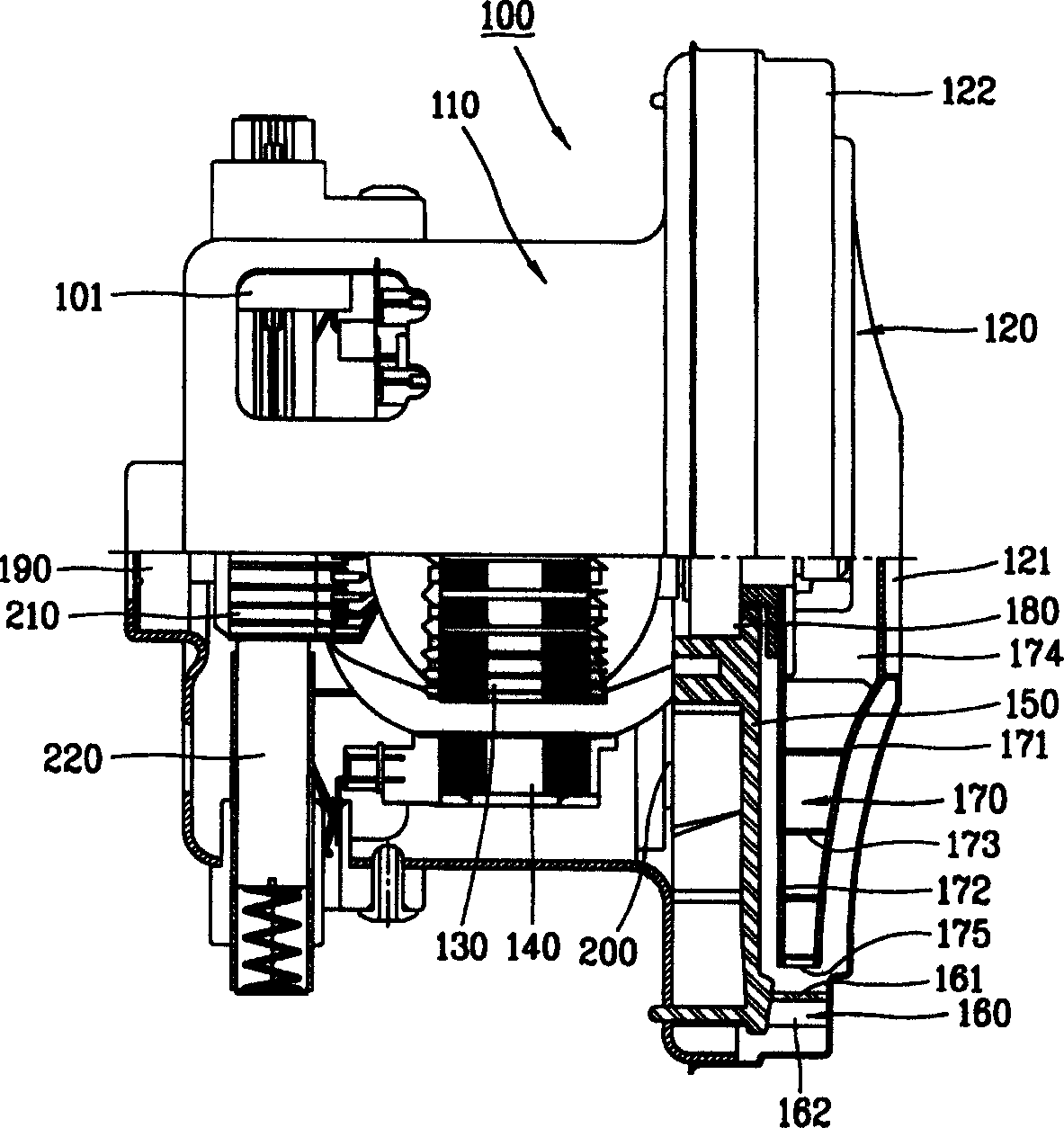
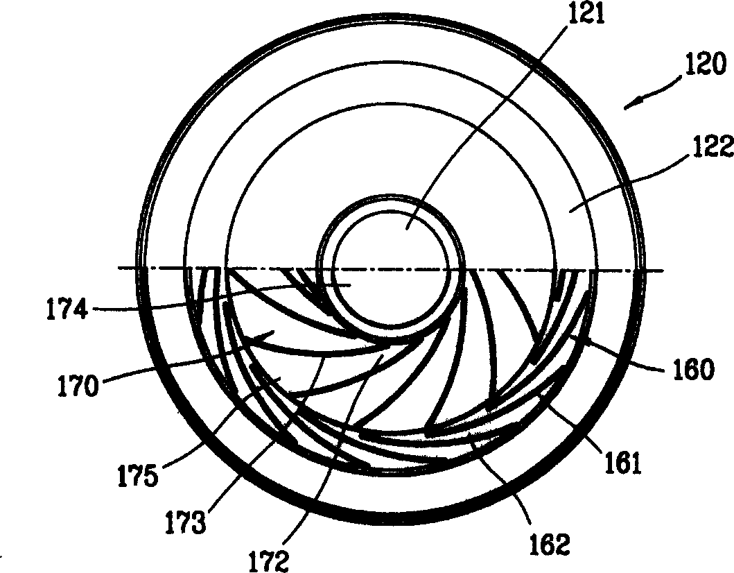
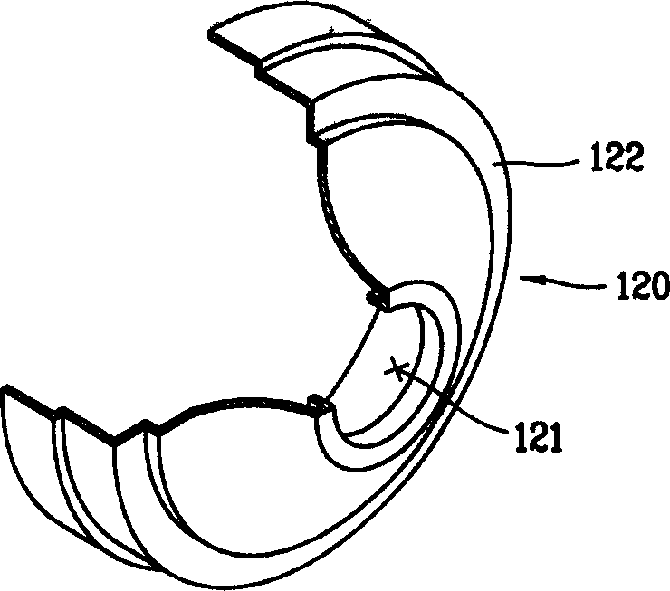
[0040] Figure 4 to Figure 6 It is a schematic diagram of an embodiment of the structure for reducing the resonance noise of the fan casing of the vacuum cleaner motor provided by the present invention. in, Figure 4 It is a half-sectional diagram of the motor for vacuum cleaner provided by the present invention; Figure 5 yes Figure 4 side view of Figure 6 It is a partial sectional view of the motor fan casing for the vacuum cleaner provided by the present invention.

[0041] Such as Figure 4 , Figure 5 , Figure 6 As shown, the vacuum cleaner motor provided by the present invention includes a motor housing 11 , a stator 14 , a rotor 13 , a motor shaft (not shown), a fan 17 , a diffuser 16 , variable spee...


PUM


Abstract

The present invention discloses a structure for reducing resonace noise of fan case for vacuum cleaner motor. Said structure includes fan outer protector which is connected with front side opening position of outer shell of vacuum cleaner motor and can be used for protecting fan, diffuser placed on the peripheral surface of the fan and diffuser sealing surface which is connected together with fan outer protector, sectional extended space which is tightly fixed on the front face of diffusion vane formed into diffuser and can reduce flow rate of air high-speed flower out from the fan and resonace-resisting circular groove which is forward projected and formed on the above-mentioned diffuser sealing surface. In the vacuum cleaner provided by said invention the structure capable of reducing motor noise is adopted, so that its product reliability also can be raised.

Description

technical field [0001] The present invention relates to an invention of a vacuum cleaner, and more specifically, relates to a structure for reducing resonance noise of a fan casing for a vacuum cleaner motor. Background technique [0002] A vacuum cleaner is a device that collects external foreign matter such as inhaled dust inside. In order to generate suction, a motor is provided inside its body. Below, combine Figure 1 to Figure 3 , for a detailed description of an existing vacuum cleaner. [0003] figure 1 It is a half sectional view of a conventional vacuum cleaner motor. figure 2 yes figure 1 side view. image 3 It is a partial cross-sectional view of a fan housing for a conventional vacuum cleaner motor. [0004] Such as figure 1 , figure 2 , image 3 As shown, the motor 100 of the existing vacuum cleaner includes a motor housing 110 , a stator 140 , a rotor 130 , a motor shaft (not shown), a fan 170 , a diffuser 160 , variable speed guide vanes 150 , a...

Claims


Application Information

Patent Timeline
Patent Type & Authority Applications(China)
IPC IPC(8): A47L5/12F04D29/66
Inventor 南贤植
Owner LG ELECTRONICS (TIANJIN) APPLIANCES CO LTD
Why Eureka
Try Eureka