
Arrangement for connecting two circuit boards by connector, coplanar structural section and microstrip structural section

A technology for circuit boards and connectors, applied in circuit devices, circuits, printed circuits, etc., can solve problems such as volume and price reduction, transmission power loss, etc.

Inactive Publication Date: 2004-10-20
赛罗恩法国两合公司
View PDF0 Cites 0 Cited by
  • Summary
  • Abstract
  • Description
  • Claims
  • Application Information

AI Technical Summary

Problems solved by technology

[0016] However, although the size and price of this connector is lower than that of coaxial cable, the connection using this connector will result in the loss of transmitted power

Method used


Image

  • Arrangement for connecting two circuit boards by connector, coplanar structural section and microstrip structural section
  • Arrangement for connecting two circuit boards by connector, coplanar structural section and microstrip structural section
  • Arrangement for connecting two circuit boards by connector, coplanar structural section and microstrip structural section

Examples


Embodiment Construction

[0048] To describe the invention, the symbols V, L, T are shown in the figures in a non-limiting manner, denoting vertical, longitudinal and transverse directions, respectively.

[0049] The longitudinal direction and the left-to-right direction are also denoted by a top-to-bottom direction, as shown in FIG. 2 .

[0050] In the following description, the same, similar and similar parts are denoted by the same numerals.

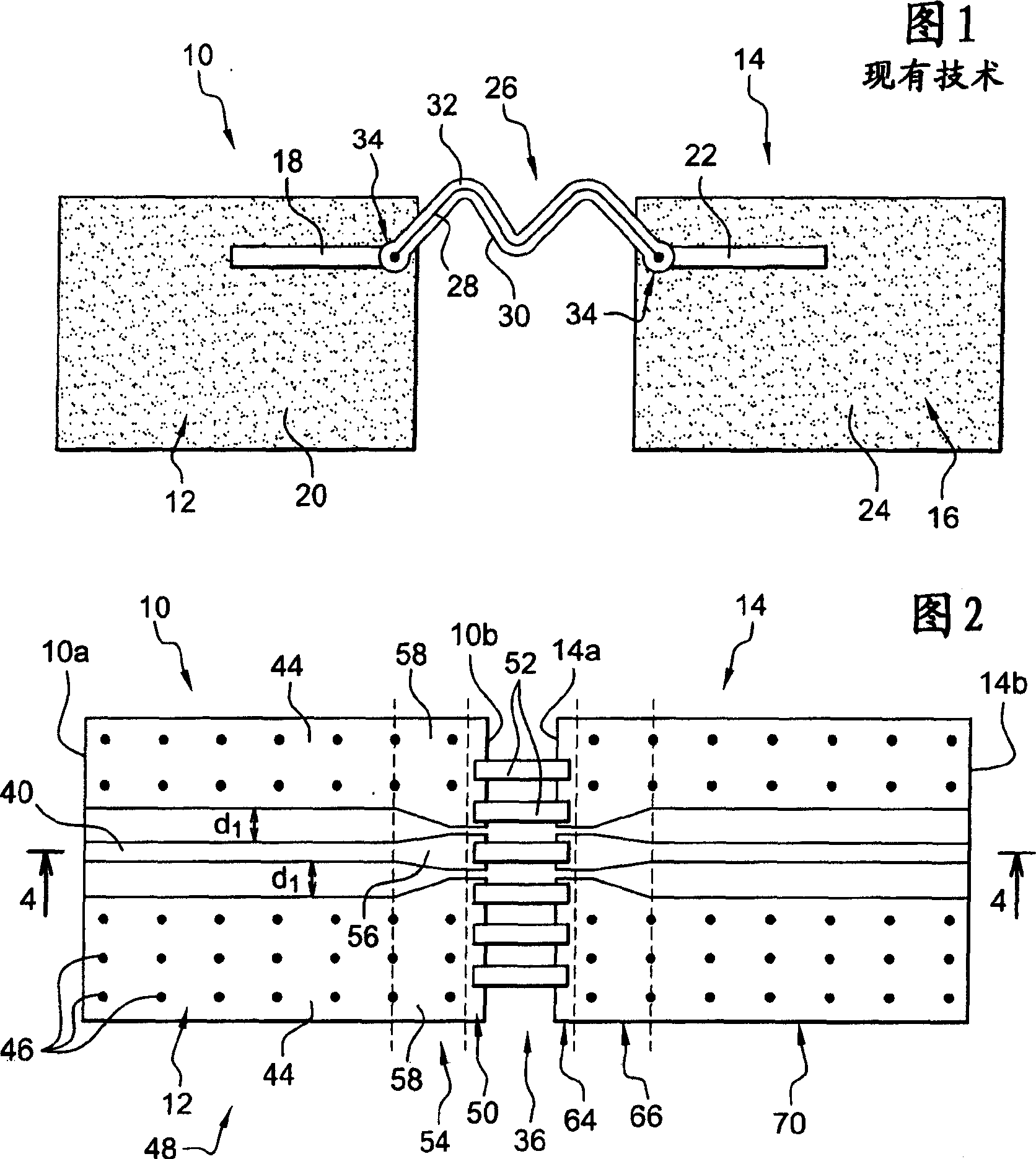
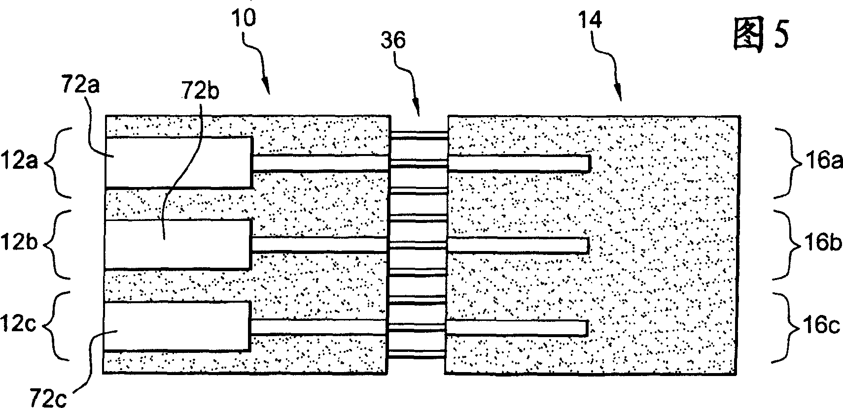
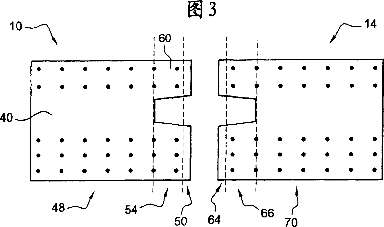
[0051] Two electronic modules or circuit boards 10, 14 are shown in FIG.

[0052] According to a preferred embodiment, the connector 36 is a zero insertion force type connector, generally called a ZIF connector, but the connector 36 can also be of any other type, as commonly called a LIF connector (i.e. Low Insertion Force) weak insertion force connectors.

[0053] The two modules 10, 14 are the two elements of the antenna of the portable radiotelephone for transmitting and receiving electromagnetic waves.

[0054] The antenna also includes a plurality of e...


PUM


Abstract

The arrangement has an electronic substrate (10) with a contact zone (50) arranged at a side of a connector (36). A matching section (54) in the substrate connects a microstrip line (48) to the zone for modifying direction of electromagnetic field between the line and zone, in parallel to direction of electric field in the connector. The connector may be a zero insertion force (ZIF) or low insertion force (LIF) connector. An Independent claim is also included for a portable radio-telephone.

Description

technical field [0001] The present invention proposes an arrangement for connecting two electronic modules through a zero insertion force or weak insertion force type connector. [0002] The invention proposes, inter alia, an arrangement for electrically connecting two circuit boards, in which arrangement an electromagnetic wave transmission line is printed on each circuit board, at least one transmission line of the first circuit board printed in a microstrip configuration, so The arrangement includes a connector consisting of a row of longitudinal pins connecting the transmission lines of the two circuit boards. Background technique [0003] The current trend related to wireless handheld telephones is to reduce the external dimensions of the telephones. Therefore, the size of various printed circuits is also reduced. [0004] The effectiveness of an electromagnetic wave transmitting / receiving antenna depends in part on the area of ​​the ground circuit of all printed circ...

Claims


Application Information

Patent Timeline
IPC IPC(8): H01P1/04H01R12/04H05K1/02H05K1/14
CPCH05K1/0219H05K2201/09336H05K2201/0715H05K1/0237H05K2201/09727H01P1/047H05K1/142
Inventor 格温奈尔·吉瓦
Owner 赛罗恩法国两合公司
Learn More