Headlamp of vehicle

A technology for headlights and vehicles, which is applied to vehicle lighting systems, headlights, vehicle components, etc., can solve the problems of delicate control, difficulty in the shape of light distribution patterns and brightness distribution, and achieve the effect of suppressing glare.

Inactive Publication Date: 2004-10-27
KOITO MFG CO LTD
View PDF2 Cites 18 Cited by
  • Summary
  • Abstract
  • Description
  • Claims
  • Application Information

AI Technical Summary

Problems solved by technology

[0006] When the linear light source device disclosed in the above-mentioned "Patent Document 2" is applied to a vehicle headlamp, a light distribution pattern with a horizontal cut-off line can also be formed at the upper end, but at this time there is a difference in the light distribution pattern. The shape and brightness distribution are difficult to finely control

Method used


Image

  • Headlamp of vehicle
  • Headlamp of vehicle
  • Headlamp of vehicle

Examples


Embodiment Construction

[0030] Embodiments of the present invention will be described below with reference to the accompanying drawings.

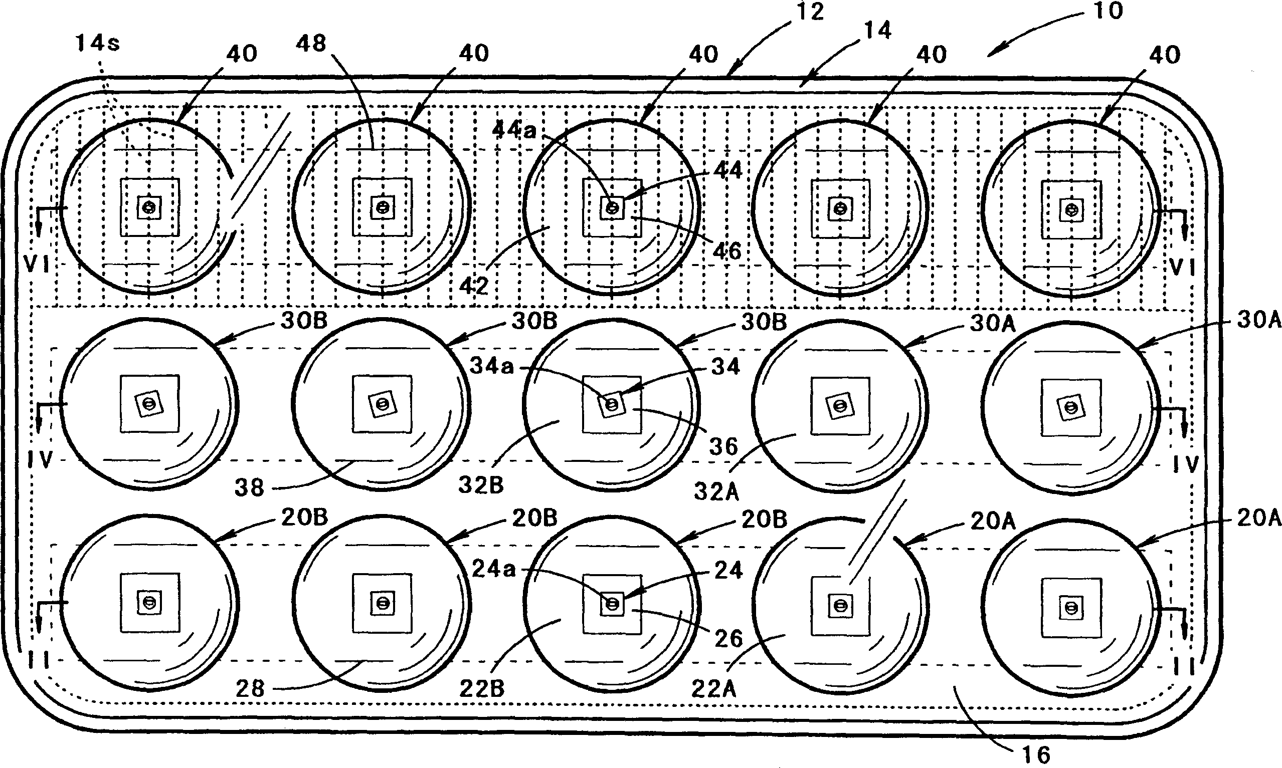
[0031] figure 1 It is a front view showing a vehicle headlamp according to an embodiment of the present invention.

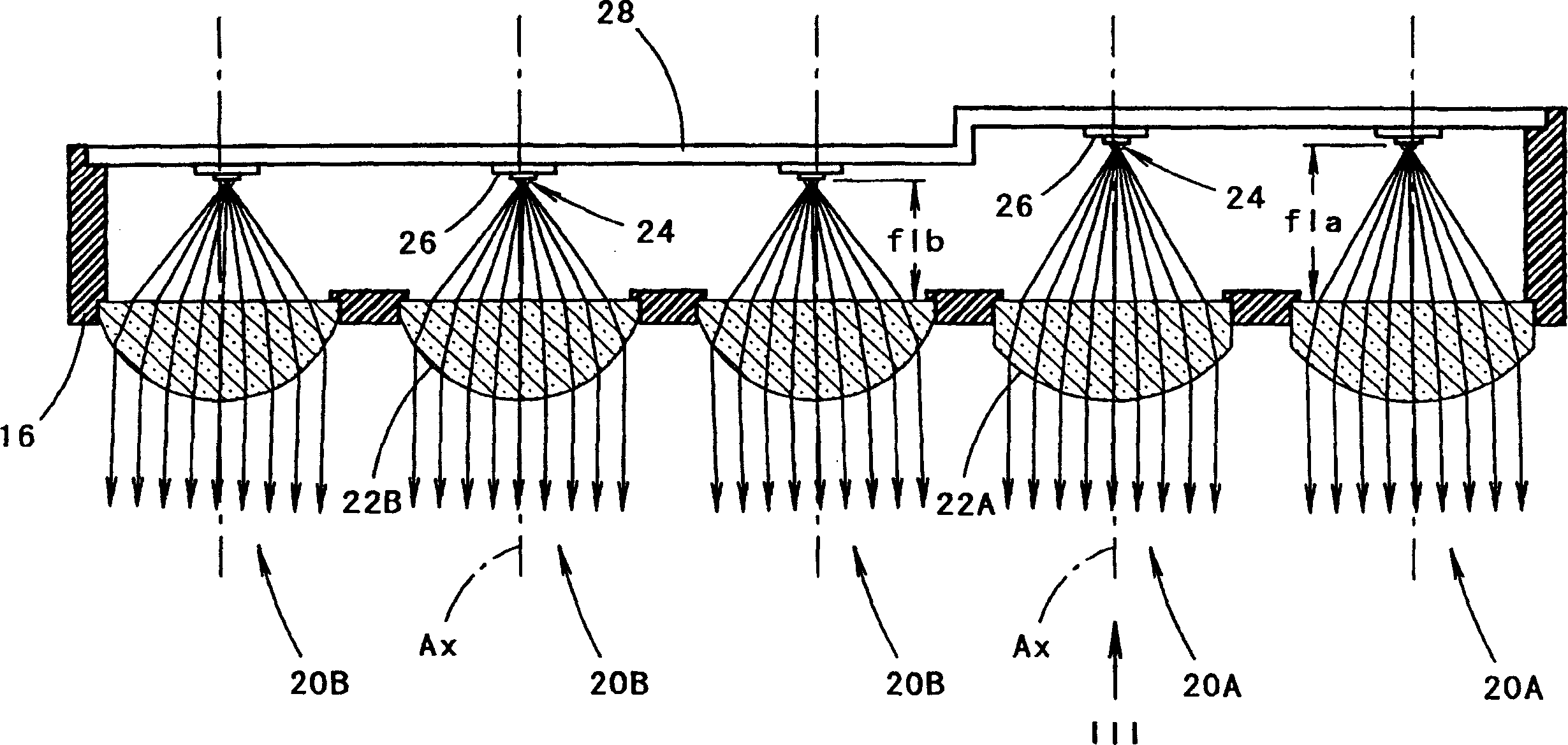
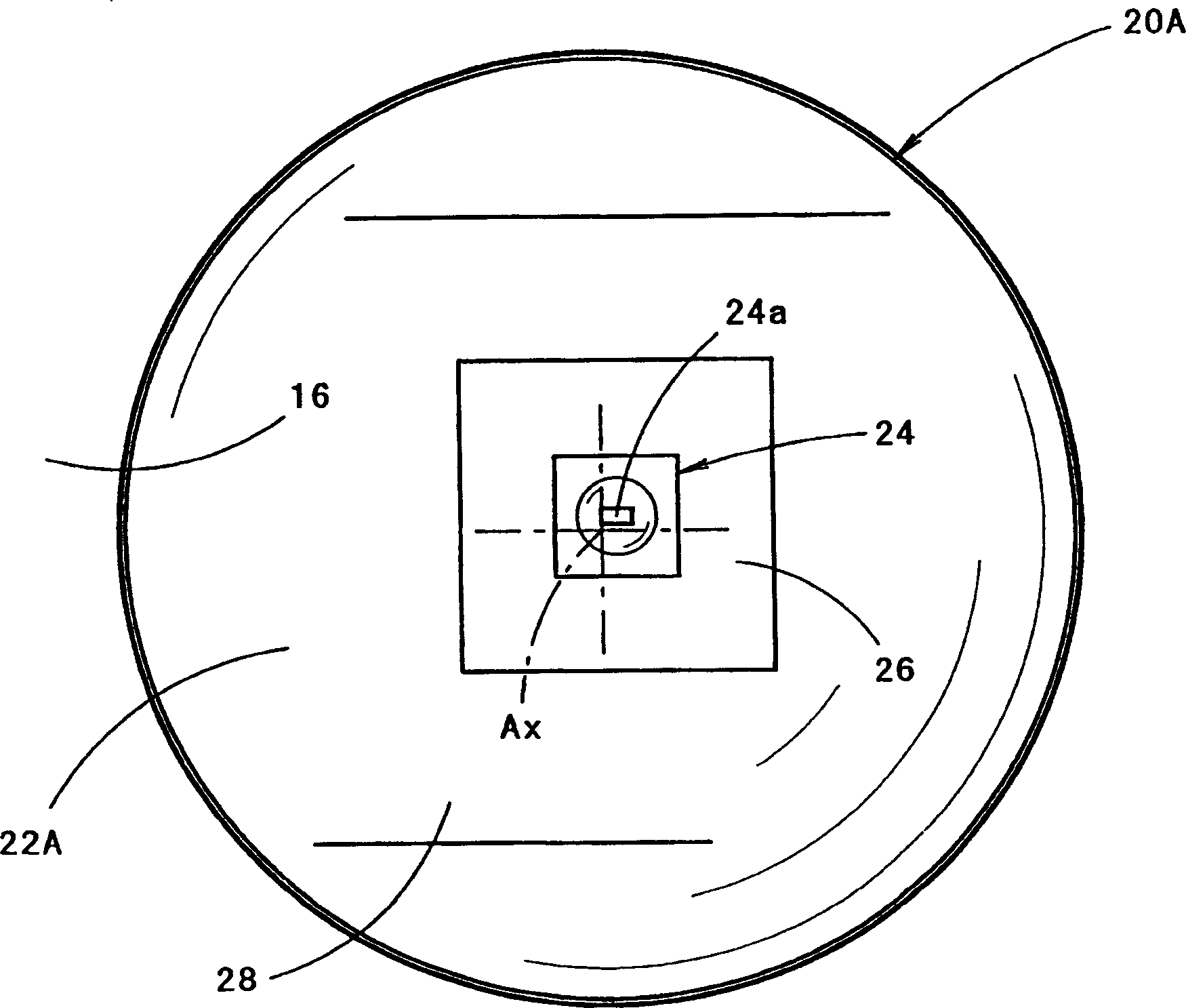
[0032] As shown in the figure, the vehicle headlamp 10 of the present embodiment accommodates 15 lamp units in three upper and lower layers in the lamp chamber formed by the lamp body 12 and the translucent cover 14 attached to the opening at the front end thereof. structure. That is, five first lamp units 20A, 20B are arranged on the lower floor, five second lamp units 30A, 30B are arranged on the middle floor, and five third lamp units 40 are arranged on the upper floor.

[0033] Most of the translucent cover 14 is transparent, and the upper area is formed into vertical stripes by a plurality of diffusion lens elements 14s, which are used to diffuse the illumination light from the five third lamp units 40 located on the upper floor to the horizo...


PUM


Abstract

There are provided five first lighting units for carrying out light irradiation to form a horizontal cutoff line. Each of the first lighting units has such a structure that includes a first light source formed by a light emitting diode provided to face forward in such a manner that one side of a rectangular light emitting chip is extended in a horizontal direction, and first projection lenses provided in front thereof and serving to project the image of the first light source as an inverted image forward from the lighting units. Consequently, the inverted image of the first light source projected forward from the lighting unit is an almost rectangular image having an upper edge extended almost horizontally. These are provided with a shift from each other in the horizontal direction, thereby forming a horizontal cutoff line. Two additional rows of lighting units provide light for an oblique cutoff line and a diffuse light pattern, respectively.

Description

technical field [0001] The present invention relates to a vehicle headlamp, which has a structure in which a light distribution pattern with a horizontal cut-off line is formed on the upper end. Background technique [0002] Currently known is a vehicle headlamp disclosed in, for example, Patent Document 1, in which a light distribution pattern having a horizontal cut-off line is formed at an upper end portion by light irradiation from a plurality of lamp units. [0003] "Patent Document 2" discloses a linear light source device configured to reflect light from a linear light source in which a plurality of light emitting diodes are linearly arranged by a predetermined reflective member. [0004] Patent Document 1: JP-A-2001-270383 [0005] Patent Document 2: JP-A-2003-31011 [0006] When the linear light source device disclosed in the above-mentioned "Patent Document 2" is applied to a vehicle headlamp, a light distribution pattern with a horizontal cut-off line can also b...

Claims


Application Information

Patent Timeline
Patent Type & Authority Applications(China)
IPC IPC(8): B60Q1/04F21S8/10F21S8/12F21V5/04F21V13/00F21W101/10F21Y101/02
CPCY10S362/80F21S48/1154F21S48/1163F21S48/1747F21Y2101/02F21V5/04F21S41/143F21S41/153F21S41/155F21S41/663F21Y2115/10
Inventor 石田裕之
Owner KOITO MFG CO LTD
Why Eureka
Try Eureka