Heat sink and structure of fan frame

A technology of heat dissipation device and fan frame, which is applied in the direction of instruments, electrical digital data processing, electrical components, etc., can solve the problems of narrowed side flow channels, limited air intake, and limited shape of fan blades, so as to enhance the heat dissipation effect and improve the heat dissipation. Efficiency, the effect of increasing air flow

Inactive Publication Date: 2004-10-27
DELTA ELECTRONICS INC
View PDF0 Cites 1 Cited by
  • Summary
  • Abstract
  • Description
  • Claims
  • Application Information

AI Technical Summary

Problems solved by technology

[0004] However, due to the limitation of the size of the square outer frame, the traditional fan has to reduce the side flow channel, and the shape of the fan blade is also limited. It cannot be optimally designed with the flow channel curve, and the space of the fan frame is wasted. with material
In addition, due to the limitation of the fan frame, only vertical (or axial) air intake can be made, or the arc angle can be increased, but the increased air intake is still limited

Method used


Image

  • Heat sink and structure of fan frame
  • Heat sink and structure of fan frame
  • Heat sink and structure of fan frame

Examples


Embodiment Construction

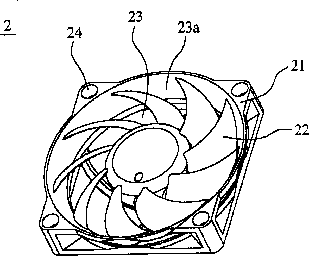
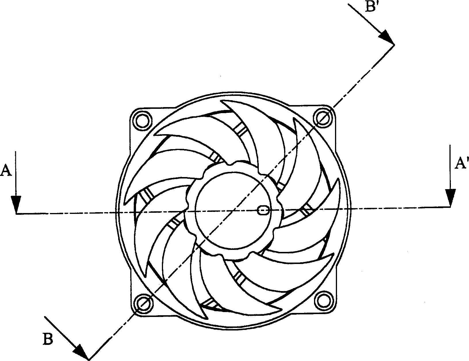
[0037] see Figure 2A to Figure 2D , which is the first preferred embodiment of the cooling device of the present invention, the cooling device 2 is mainly composed of a fan frame structure and an impeller 22, the fan frame structure has a square frame 21, including an air inlet, a The air outlet and a channel 23 connecting the air inlet and the air outlet, the inner peripheral wall 23a of the channel extends radially outward with the central axis of the heat sink or the channel as the center, or even partially protrudes outside the square outside box 21. Since the air inlet end of the fan frame structure expands outwards in a circular shape, the shape of the bottom of the fan frame structure is still maintained as a square shape, and its screw holes 24 and hole positions also remain unchanged, so that the way of assembling with other components is also the same. Follow unchanged. With the outward expansion of the inner peripheral wall of the fan frame structure, the size of...


PUM


Abstract

The structure of fan frame includes a channel to induct airflow from an opening to another opening. Inner circumference wall pathway of at least one opening is extended and outspread towards outside along radial by using the axis of the heat sink or channel as center in order to increase air effluent or influent area. Thus, in and out air quantities are increased largely without need of changing other assembling condition so as to raise heat dispersion.

Description

technical field [0001] The invention relates to a cooling device and its fan frame structure. In particular, it relates to an axial flow fan and its fan frame device which can increase the air intake without changing the assembly condition with other components, thereby greatly improving the heat dissipation effect of the fan. Background technique [0002] In order to avoid being polluted by dust in the atmosphere, common electronic products usually place electronic components in relatively closed casings. However, since electronic components (such as a central processing unit (CPU) or a circuit board) will generate high temperature during operation, if they are kept in a high temperature state, it will easily lead to wear and tear of the components and shorten their lifespan. Therefore, in order to prevent electronic components from malfunctioning, cooling fans are generally provided therein to dissipate the internal high temperature to the outside. [0003] see figure 1...

Claims


Application Information

Patent Timeline
Patent Type & Authority Applications(China)
IPC IPC(8): G06F1/20H01L23/36
Inventor 柯皓文雷宗玙林国正张秀贞
Owner DELTA ELECTRONICS INC
Why Eureka
Try Eureka