Automatic dust-removing apparatus for electric dust remover

A technology of automatic dust removal and electrostatic precipitator, which is applied in the direction of electrostatic separation to achieve the effect of ensuring installation, reducing difficulty and labor intensity, and improving dust removal efficiency

Inactive Publication Date: 2004-11-03
国营浙南环保工程机械厂 +1
View PDF0 Cites 7 Cited by
  • Summary
  • Abstract
  • Description
  • Claims
  • Application Information

AI Technical Summary

Problems solved by technology

However, it is also because of well-known reasons: the current dust collection cylinder is rigidly connected, and the method of tangential vibration cleaning has to be used.
This is also an inevitable defect in the operation of the traditional dry bobbin structure electrostatic precipitator

Method used


Image

  • Automatic dust-removing apparatus for electric dust remover

Examples


Embodiment Construction

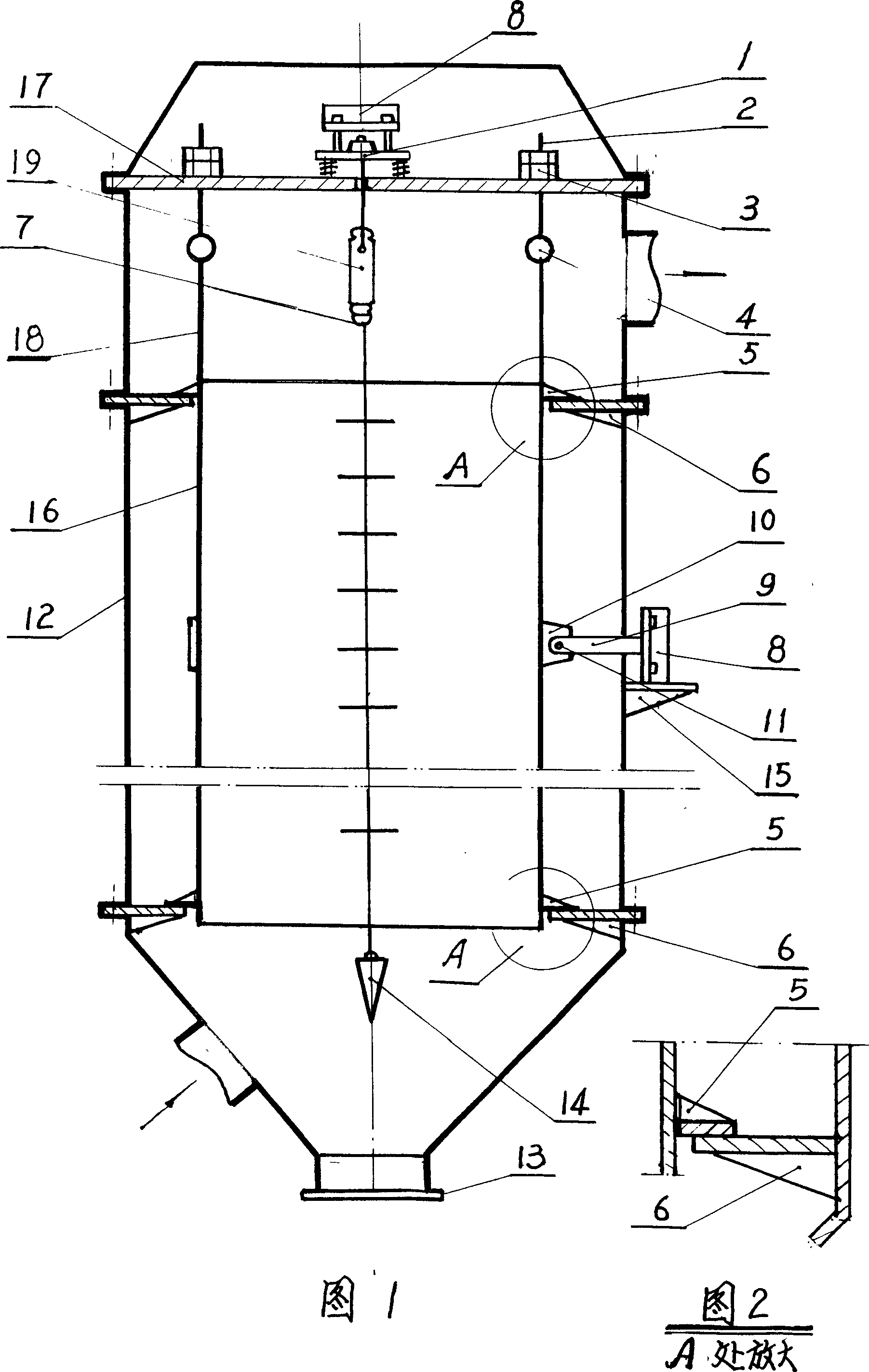
[0011] In Fig. 1, the corona wire (7) connects the weight (14) and the insulator (19), and hangs vertically on the corona pole support (1) through the cover plate (17), and the corona wire (7) is running The center must be kept consistent with the distance from the inner wall of the dust collection cylinder (16), and its coaxiality tolerance is ±5mm, otherwise, the electrostatic precipitator efficiency will obviously drop, or even not work. The dust collection cylinder (16) is connected with 4 suspension rods (18) at the top, and relies on 4 suspension rings (4) to be connected with 4 suspension screw rods (2) passing through the cover plate (17). The screw rods (2) are respectively An adjusting nut and a lock nut (3) are screwed. During operation, adjusting this set of nuts can adjust the verticality deviation of the dust collection cylinder (16) so that it remains coaxial with the corona wire (7) all the time, ensuring Dust removal efficiency. The upper end, the middle part...


PUM


Abstract

The automatic electric dust remover is used for electric dusting apparatus in dry barrel structure and adopts the kernel technology of altering traditional fixed dust collecting barrel into suspended one below the cover plate of the electric duster by means of regulating screws, hanging rings and hanging rods and with adjustable verticality. In the same time, the flange ring and figured plate around the dust collecting barrel may be slided horizontally to match the vibration mechanism for horizontal vibration to remove dust.

Description

Technical field [0001] The invention relates to a dry bobbin structure electrostatic precipitator widely used in modern industry, in particular, the traditional fixed dust collecting cylinder (or dust collecting cylinder, dust collecting electrode) is changed into a suspended The sliding dust collection cylinder enables the effective implementation of the horizontal rapping dust removal technology, which significantly improves the efficiency of electrostatic precipitator, increases the maintenance performance, and prolongs the service life. Background technique [0002] The well-known technology of using static electricity to attract fine dust particles and purify industrial waste gas was successfully born at the beginning of the last century (1907). Its advantages are: high dust removal efficiency, can adapt to high temperature, a large amount of flue gas, the collected dust particles Compared with other industrial dust collectors such as: cyclone dust collector, Venturi tu...

Claims


Application Information

Patent Timeline
IPC IPC(8): B03C3/88
Inventor 顾庭康
Owner 国营浙南环保工程机械厂
Why Eureka
Try Eureka