Coil type turn-fin condenser

A technology of helical fins and helical finned tubes is applied in the field of coil type helical finned condensers, which can solve the problems of reducing the amount of surrounding air, reducing heat exchange efficiency, and large installation space.

Inactive Publication Date: 2004-11-03
KOREA BUNDY
View PDF0 Cites 10 Cited by
  • Summary
  • Abstract
  • Description
  • Claims
  • Application Information

AI Technical Summary

Problems solved by technology

[0008] However, there is a problem in that, since the curved condenser is manufactured by bending the spiral fin tube 1 twice to complete the primary bending and secondary bending, the manufacturing process is complicated, and since the air flows between the spiral fin tubes 1 The motor 4 and blower fan 5 protrude outward, thus requiring a large installation space
[0009] And, when the ambient air sucked by the blower fan 5 flows over the outer surface of the spiral finned tube 1, since the spiral finned tube 1 bends forward and backward and upward and downward, the air and the spiral fin 1b have a large The contact area, but due to the air resistance generated by the overlapping structure with many folds, the amount of ambient air in contact with the spiral fin 1b is reduced, thereby reducing the heat exchange efficiency

Method used


Image

  • Coil type turn-fin condenser
  • Coil type turn-fin condenser
  • Coil type turn-fin condenser

Examples


Embodiment 1

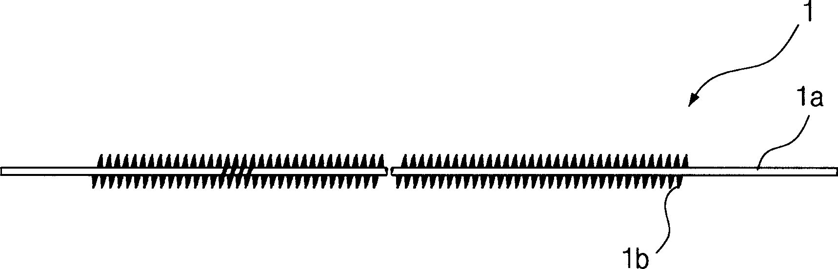
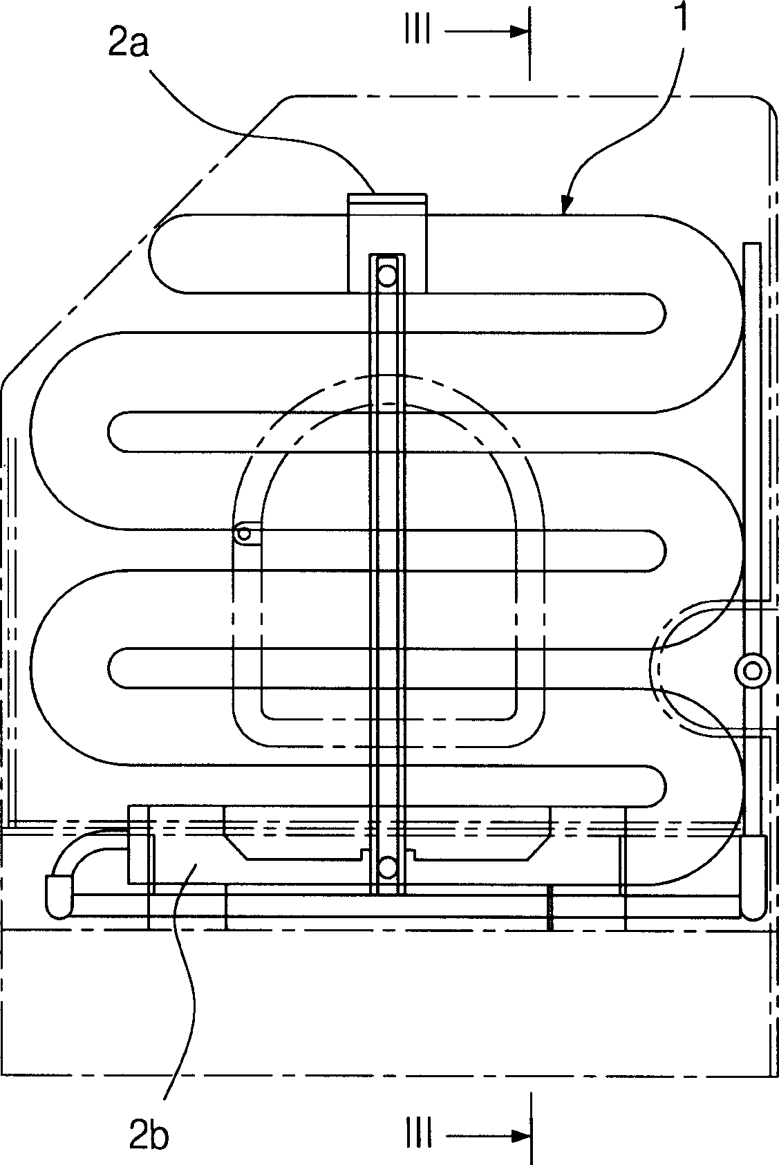
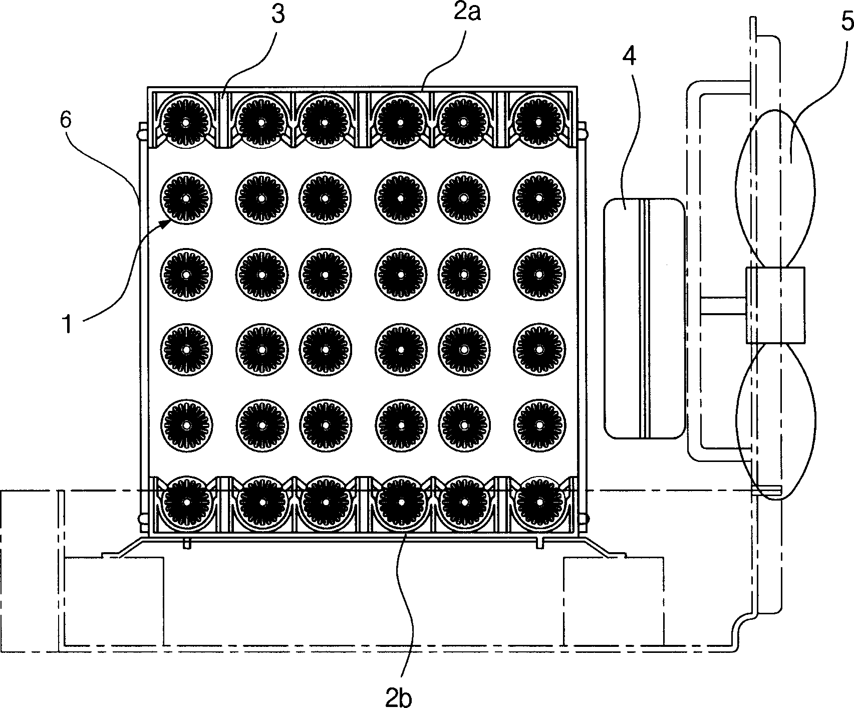
[0030] see Figure 4 and 5 , the coil type spiral fin condenser of the present invention has the spiral fin tube 10 (hereinafter also referred to as " spiral fin tube coil ") of circular coil shape, is wound around the tube 11 that flows through refrigerant, and spiral fin 12 Wound tightly on the outer surface of the tube 11 in a helical shape. On the inner and outer surfaces of the helically finned tube coil, the helically finned tube 10 has an inner frame 20 and an outer frame 30, respectively, both of which are strip-shaped. The inner support 20 and the outer support 30 respectively form arc-shaped grooves repeatedly for receiving the helical fins 12 .

[0031] In the internal space formed by the spiral fin tube coil 10, the coil type spiral fin condenser is equipped with a blower fan 50 for sucking ambient air into the spiral fin tube coil and a motor 40 for driving the blower fan 50. The motor 40 is installed in the inner space of the coil, and is connected with the su...

Embodiment 2

[0046] see Figure 9 , The coil-type spiral-fin condenser according to the present invention has a plurality of coils, including an inner coil 15 and an outer coil 16, in order to enhance the heat exchange efficiency of the condenser.

[0047] Each of the inner coil 15 and the outer coil 16 is formed of a helically finned tube 10 wound around a tube 11 in which a heat exchange medium flows, and a helical fin 12 is tightly wound on an outer surface of the tube 11 in a helical shape.

[0048] Embodiment 2 has the same components as Embodiment 1 except for the inner coil 15 and the outer coil 16 . Therefore, detailed descriptions of the same parts are omitted below.

[0049] There is a gap between adjacent outer coil surfaces of the outer coil 16 through which ambient air can flow. The inner coil 15 is located inside the outer coil 16 and separated from the outer coil 16 by a predetermined distance. There is also a gap between adjacent coil outer surfaces of the inner coil 15 t...


PUM


Abstract

Disclosed herein is a turn-fin condenser. The turn-fin condenser employs a turn-fin tube adhesively wound in a spiral shape around an outer surface of the tube in which refrigerant flows. The condenser comprises a coil type turn-fin tube 10 wound in a coil shape and fixed by inner and outer brackets 20 and 30 surrounding an outer peripheral surface of the coil type turn-fin tube, a motor 40 positioned in an inner space formed by the coil type turn-fin tube 10, a blowing fan 50 for taking ambient air in the coil type turn-fin tube 10 after being driven by the motor 40, and a tube wall 80 spirally wound with tube 11 extending out of the inner and outer brackets 20 and 30 at the rear side of the coil type turn-fin tube 10. The turn-fin condenser is easily manufactured and allows a greater quantity of air contact with turn-fins, thereby enhancing heat exchange efficiency.

Description

technical field [0001] The present invention relates to spiral fin condensers, and more particularly to coil type spiral fin condensers which are easy to manufacture and include a structure which allows more air to contact the spiral fins, thereby improving heat exchange efficiency. Background technique [0002] Generally, the condenser of the air conditioner is used to dissipate the heat in the high-temperature, high-pressure gas-phase refrigerant discharged from the compressor, and then use high pressure to liquefy the gas-phase refrigerant. In recent years, all major industrialized countries have tightened energy efficiency regulations. As a result, as a method of significantly improving cooling efficiency and reducing energy consumption in the fields of refrigerators, freezers, and air conditioners, a condenser using a spiral fin is mainly used instead of a heat exchanger having a wire tube shape. [0003] Such as figure 1 As shown, the traditional spiral finned tube ...

Claims


Application Information

Patent Timeline
Patent Type & Authority Applications(China)
IPC IPC(8): F28F1/36F25B39/04F28D1/047F28D7/02F28F9/013F28F9/26
CPCF28F9/0132F25B39/04F28F1/36F28D7/024
Inventor 李东河任文宰
Owner KOREA BUNDY
Why Eureka
Try Eureka