Image forming apparatus for preventing image deterioration caused by fallen conductive brush and scatter of developer

An image and latent image carrier technology, which is applied in corona discharge devices, electric recording technology using charge patterns, equipment for electric recording technology using charge patterns, etc., can solve problems such as difficult to meet, and prevent electrostatic potential like disordered effect

Inactive Publication Date: 2004-11-03
RICOH KK
View PDF5 Cites 0 Cited by
  • Summary
  • Abstract
  • Description
  • Claims
  • Application Information

AI Technical Summary

Problems solved by technology

However, due to reasons such as the diameter of the developer carrying body, the arrangement of the magnetic poles, and the diameter of the photoreceptor, it is sometimes difficult to satisfy the requirement of disposing the developer scatter prevention member of the above-mentioned Patent Document 1 in close contact with the photoreceptor at the top end of the developer scatter prevention member. above conditions

Method used


Image

  • Image forming apparatus for preventing image deterioration caused by fallen conductive brush and scatter of developer
  • Image forming apparatus for preventing image deterioration caused by fallen conductive brush and scatter of developer
  • Image forming apparatus for preventing image deterioration caused by fallen conductive brush and scatter of developer

Examples


no. 1 example

[0116] Figure 10 and Figure 11 It is an explanatory diagram of the installation position of the main development magnetic pole P1b of the magnetic roller 41, and the installation position of the main development magnetic pole P1b of the magnetic roller 41 is preferably 3° to 9° upstream in the developer conveying direction from the position closest to the development nip.

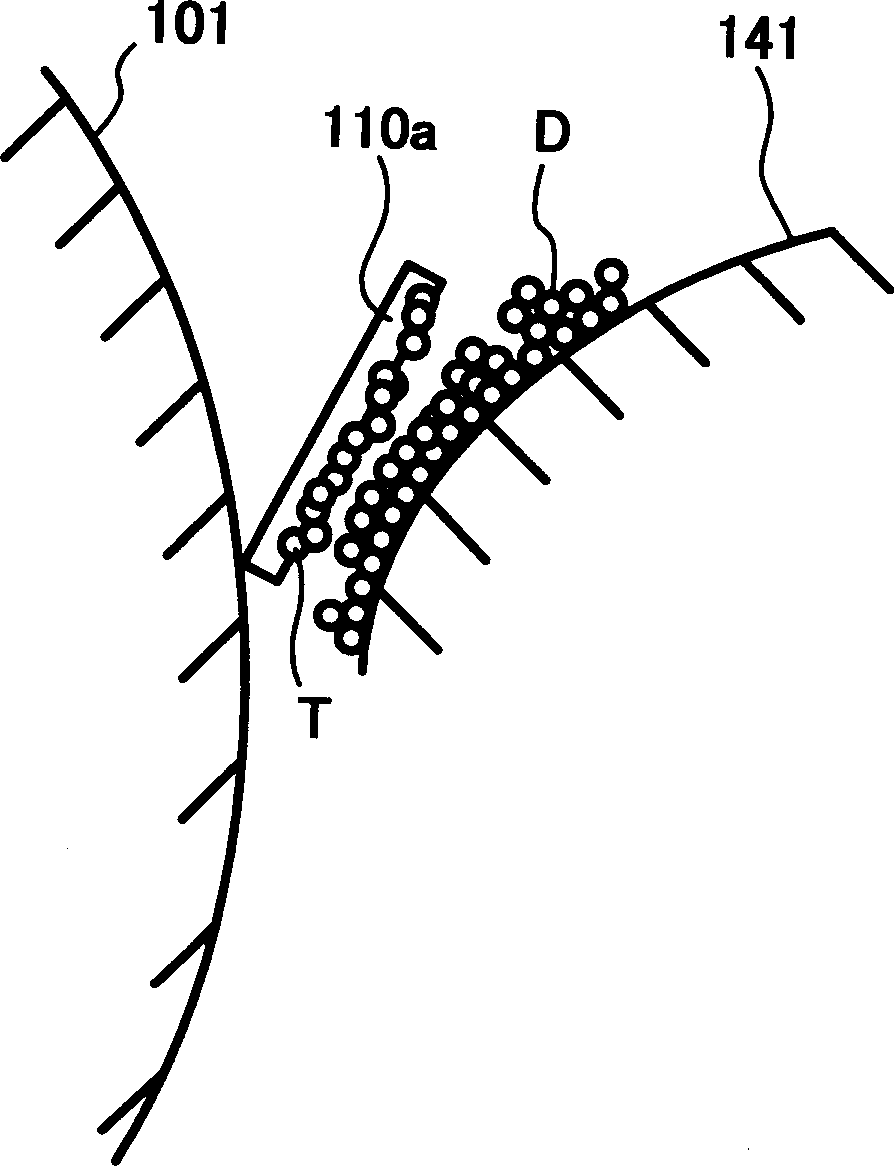
[0117] If the main pole angle is less than 3°, for example Figure 10 Among them, the main magnetic pole angle of the magnetic roller is 0°, the ends of the first inlet seal 10a and the second inlet seal 10b face the auxiliary magnetic pole P1a, and the magnetic ears of the magnetic brush caused by the auxiliary magnetic pole P1a stand up and contact the photoreceptor. Drum 1 is connected. Therefore, the magnetic brush due to the auxiliary magnetic pole P1 a and the magnetic brush due to the developing main magnetic pole P1 b rub the electrostatic latent image on the photoreceptor drum 1 , and the image...

no. 2 example

[0137] In order to confirm the effect of the structure of the present invention described above, an evaluation test was performed, and the thickness Y1 of the first inlet seal 10 a and the thickness Y2 of the second inlet seal 10 b were both set to 0.2 mm. In this evaluation test, cut off a quarter of the brush from the brush roller 2b, make it attached to a new brush roller 2b, carry out 500 copying tests each, and count the number of sheets with abnormal images. The results are listed in Table 2.

[0138] Developing roller condition

The number of images with abnormal black stripes

Conventional developing roller

500 / 500

This example

developing roller

Main pole angle 0°

186 / 500

Main Pole Angle 3°

3 / 500

Main Pole Angle 6°

0 / 500

Main Pole Angle 9°

3 / 500

Main Pole Angle 12°

256 / 500

[0139] In Table 2, "the developing roller of this example" means Figure 10 and Figure 11 The developing ...

no. 3 example

[0163] The test conditions are as follows:

[0164] Developing gap Gp: 0.4mm

[0165] Developer uptake ρ: 90mg / cm 2

[0166] Toner particle size: 6.5μm

[0167] Carrier particle size: 50μm

[0168] Linear speed Vs of photosensitive drum 1: 330 mm / sec

[0169] Diameter φ of photoreceptor drum 1: 100mm

[0170] Linear velocity ratio of the developing roller 41 to the photoreceptor drum 1: 2.0

[0171] Diameter φ of developing roller 41: 25 mm

[0172] When the linear velocity of the developing roller 41 is equal to or less than 250 mm / sec, it can be confirmed that developer scattering does not occur near the developing area, but when the linear velocity of the developing roller 41 exceeds 250 mm / sec, developer scattering occurs, and the first inlet is sealed. Item 10a becomes necessary.

[0173] Here, the inventors of the present invention conducted experiments using the above copier, and the image quality deteriorated over a long period of use. As a result of research ...


PUM


Abstract

An image forming apparatus includes a latent image carrier, a charging member, a conductive brush member that cleans the charging member, a developer carrier including magnetic field generating devices having main and auxiliary magnetic poles, a developer scatter preventing member, and a toner accumulation preventing member. A contact pressure of an end portion of the developer scatter preventing member relative to the latent image carrier is set such that a brush, which falls from the conductive brush member and is carried on the latent image carrier, passes through a contact part between the end portion of the developer scatter preventing member and the latent image carrier. The main magnetic pole has an angular width of about 60 degrees or less between opposite pole transition points respectively positioned upstream and downstream of a flux density of the main magnetic pole in the normal direction in a developer conveying direction.

Description

technical field [0001] The present invention relates to image forming apparatuses such as copiers, printers, and facsimile machines, and more specifically, to an image forming apparatus provided with a conductive brush member. The surface of the body is uniformly charged, and the above-mentioned conductive brush member cleans the surface of the charging member. Background technique [0002] Conventionally, as an image forming apparatus, an image forming apparatus that forms an electrostatic latent image on a latent image carrier, converts the electrostatic latent image into a toner image by a developing device, and transfers the toner image onto recording paper has been widely used. , forming an image. In such an image forming apparatus, the transfer residual toner remaining on the surface of the photoreceptor after toner transfer is removed by a cleaning device including a cleaning blade or the like, and is prepared for use in a subsequent process. [0003] The photorecep...

Claims


Application Information

Patent Timeline
Patent Type & Authority Applications(China)
IPC IPC(8): G03G15/02
CPCG03G15/0225
Inventor 铃木裕次
Owner RICOH KK
Why Eureka
Try Eureka