Static countermeasure parts

A countermeasure and component technology, applied in the field of electrostatic countermeasure components, can solve problems such as the inability to use high-speed transmission circuits

Inactive Publication Date: 2004-11-03
PANASONIC CORP
View PDF1 Cites 16 Cited by
  • Summary
  • Abstract
  • Description
  • Claims
  • Application Information

AI Technical Summary

Problems solved by technology

However, at this time, there is a problem that it cannot be used in high-speed transmission circuits of tens of MHz or more

Method used


Image

  • Static countermeasure parts
  • Static countermeasure parts
  • Static countermeasure parts

Examples


Embodiment 1

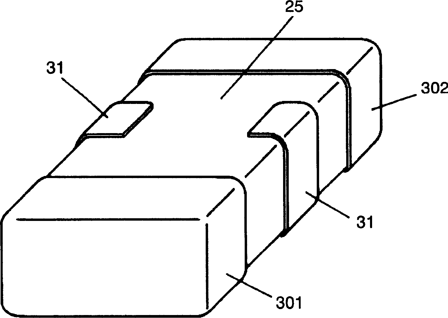
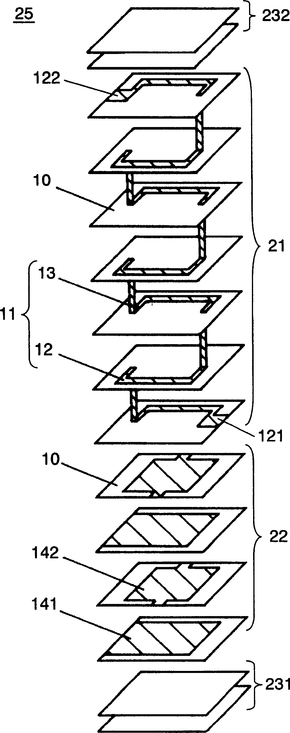
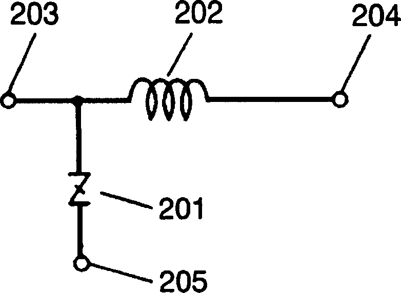
[0037] figure 1 It is a perspective view of the appearance of the static electricity countermeasure component according to Embodiment 1 of the present invention, figure 2 It is a schematic exploded perspective view showing disassembled ceramic sintered compacts constituting the static electricity countermeasure component. image 3 It is an equivalent circuit diagram of this static electricity countermeasure component.

[0038] The static electricity countermeasure component of the present invention is configured by providing input external electrodes 301 and output external electrodes 302 on both short sides of ceramic sintered body 25 and providing grounding external electrodes 31 on both long sides. figure 2 The inner structure of the ceramic sintered body 25 is shown in . The ceramic sintered body 25 is integrally formed by stacking a varistor part 22 , an inductor part 21 , and inactive layers 231 and 232 as surface protection layers.

[0039] The shape of the inducto...

Embodiment 2

[0062] Figure 10 It is a schematic exploded perspective view of the ceramic sintered body 40 constituting the static electricity countermeasure component in Example 2 of the present invention. Figure 11 This is an equivalent circuit diagram of the static electricity countermeasure component. The static electricity countermeasure component of this example differs from the static electricity countermeasure component of Example 1 in the structure of the ceramic sintered body. That is, the present embodiment is characterized in that one inductor portion and two varistor portions are formed in a ceramic sintered body. The appearance and shape of the electrostatic countermeasure parts of this embodiment are the same as those of Embodiment 1, so use figure 1 Be explained. Also, the same symbols are assigned to the same components.

[0063] The ceramic sintered body 40 constituting the electrostatic countermeasure component of this embodiment is integrally formed by stacking the...

Embodiment 3

[0082] Hereinafter, a static electricity countermeasure component according to Embodiment 3 of the present invention will be described in detail with reference to the drawings. Figure 14 It is a schematic exploded perspective view of the ceramic sintered body 50 constituting the static electricity countermeasure component of this embodiment. Figure 15 This is an equivalent circuit diagram of the static electricity countermeasure component.

[0083] The static electricity countermeasure component of this example differs from the static electricity countermeasure components of Example 1 and Example 2 in the structure of the ceramic sintered body. The present embodiment is characterized in that two inductor parts and three varistor parts are formed in a ceramic sintered body. However, the appearance of the static electricity countermeasure components of this embodiment is the same as that of the static electricity countermeasure components of Embodiment 1 and Embodiment 2, so ...


PUM

PropertyMeasurementUnit
impedanceaaaaaaaaaa
thicknessaaaaaaaaaa
thicknessaaaaaaaaaa

Abstract

A static electricity countermeasure component, which has a structure that at least an input external electrode (301), an output external electrode (302) and a grounding external electrode (31) are provided on the surface of a ceramic sintered body (25), and the ceramic sintered body ( 25) It includes: an inductor part electrically connected to the external electrode for input (301) and an external electrode for output (302), and a varistor part electrically connected to the external electrode for input (301) and the external electrode for grounding (31). Its arrangement structure is to connect an inductor to the signal line of the circuit of the electronic device, and connect a varistor between the input terminal of the signal line and the ground, so it can effectively suppress the static electricity pulse of about 0.5 to 2 nanoseconds.

Description

technical field [0001] The present invention relates to an electrostatic countermeasure component for electrostatic protection of electronic equipment. Background technique [0002] Recently, the high performance and miniaturization of electronic devices such as mobile phones are rapidly advancing, and the accompanying tendency is to lower the withstand voltage of electronic components used in the electronic devices. Therefore, damage to electronic circuits inside the equipment due to static electricity pulses that occur when the human body comes into contact with the terminals of the electronic equipment increases. This is because when static electricity is generated, a high voltage of several hundred volts to several thousand volts is generated and applied to electronic equipment within about 0.5 to 2 nanoseconds. [0003] As a countermeasure against such static electricity pulses, the proposed method is to install a varistor or a Zener diode between the line where the st...

Claims


Application Information

Patent Timeline
Patent Type & Authority Applications(China)
IPC IPC(8): H01C7/10H01C1/16H01C7/102H01C7/12H01F17/00H01F27/00H02H9/04
CPCH02H9/044H01C7/102H01C1/16H02H9/04H01C7/12H01F17/0013F16L47/08F16L47/16F16B2/08
Inventor 井上竜也德永英晃瓜生英一米田尚继织田武司
Owner PANASONIC CORP
Why Eureka
Try Eureka