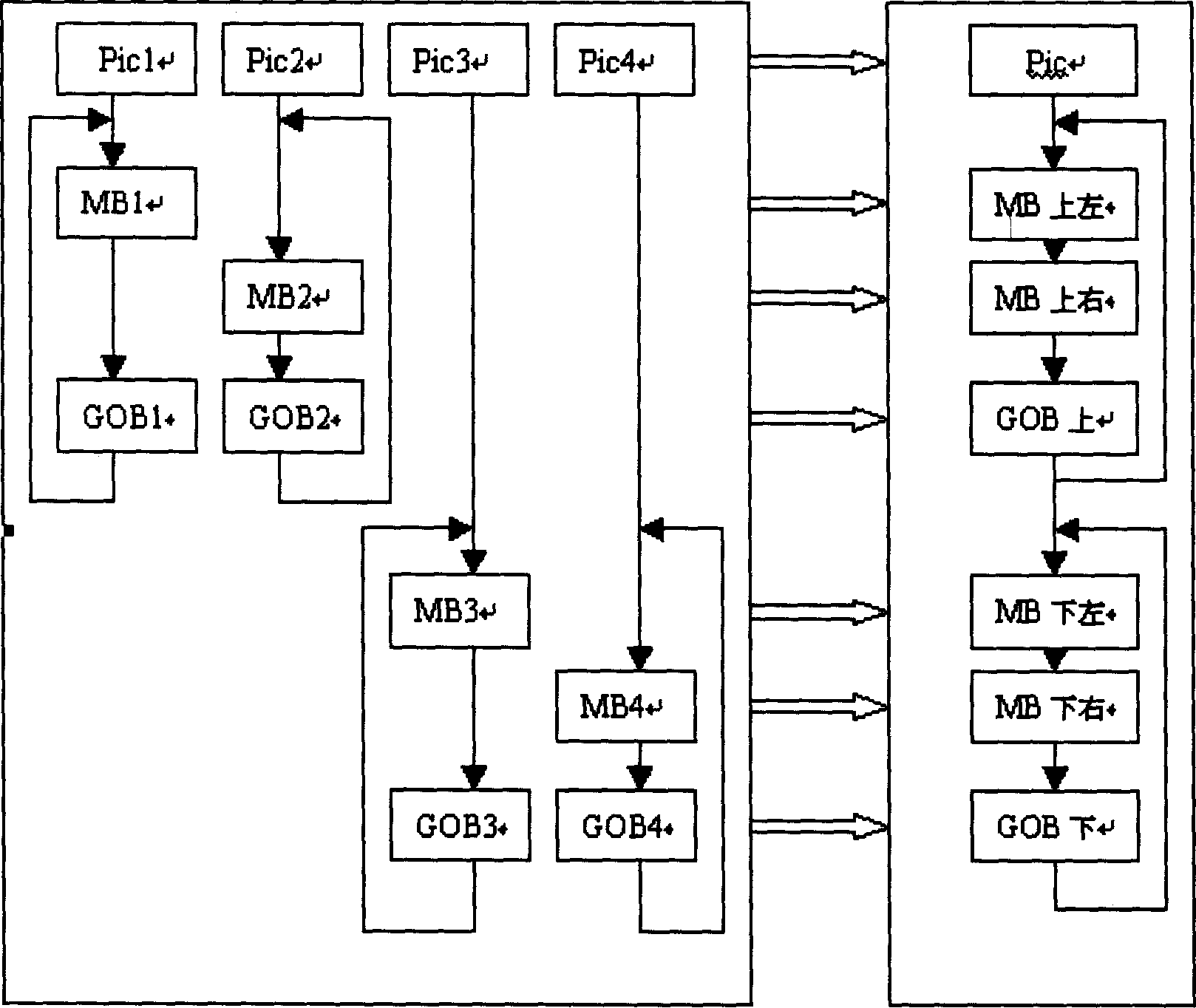
[0029] See figure 1 At the syntax level of the video stream, multiple video streams are merged together according to the mixed spatial position, for example, four QCIF streams are merged into a CIF stream, or four CIF streams are merged into a 4CIF stream , The video stream is mapped into the syntax stream of the macroblock at the corresponding position of the mixed large picture. The image header information, block group header information and macroblock header information of the mixed large picture are generated by the sub-channels participating in the mixing. figure 1 That is, it is explained that the four code streams Pic1 to 4 and the corresponding macro block layer MB1 to 4, and the block group layer GOB 1 to 4 are mapped to realize the code stream Pic and the corresponding macro block layer and block layer process. The mixing of this method is completely carried out at the code stream level, only the calculation amount of demultiplexing and multiplexing of the video stream, and a small amount of secondary quantization calculation, so the calculation complexity is greatly reduced; in addition, the distortion of the secondary encoding can also be avoided .
[0030] The key of this algorithm is how to properly use the correlation of multiple video header information to reconstruct the header information of the mixed video stream. The correlation of multi-channel video header information can be divided into three levels: image layer correlation, block group layer correlation, and macro block layer correlation.
[0031] 1) Image layer correlation: The image layer of the video stream after mixing is correlated with the image layers of the multiple video streams before mixing. Specifically include the following points:
[0032] (1) Time domain reference (TR) value correlation: Before mixing, the time domain TR values of multiple video streams are independent of each other, but after mixing, multiple TR values are required to be unified into one TR value. In this algorithm, the average of the TR values of n video streams is used as the new TR value, where n is the number of unfinished video streams. If a video stream has ended, n will be reduced by 1.
[0033] (2) Image type correlation: Because the I frame intervals of the multiple video streams before mixing are different, there will be cases where I frames and P frames are mixed into one frame. In this algorithm, the current multiple video streams are all I-frames, and they are also I-frames after mixing. Otherwise, it becomes a P frame after mixing, and all I frames before mixing are converted into Intra macroblocks of P frames after mixing.
[0034] (3) Image layer quantization step size (PQUANT) value correlation: The PQUANT value of the mixed video stream is only related to the first (upper left) video stream. In this algorithm, the PQUANT value of the video stream is directly used as the mixed PQUANT value.
[0035] 2) Relevance of the GOB: The block layer of the mixed video stream is only related to the block layer of the two video streams in the same horizontal direction before mixing, and has nothing to do with other video streams. In this algorithm, as long as there is a GOB layer in the left video stream in the same horizontal direction, there will be a GOB layer in this horizontal direction after mixing. Otherwise, there is no GOB layer. The block-level correlation also specifically includes the following points:
[0036] (1) Relevance of the GFID value of the block group layer: Because the change of GFID is synchronized with the change of the frame type (PTYPE) value, it is the image type that determines the change of the PTYPE value of the video stream after mixing. Therefore, the correlation of the GFID value is actually the correlation of the image type. In this algorithm, the mixed GFID value is directly determined according to the I.P frame type of the mixed video stream.
[0037] (2) The correlation of the quantization step size (GQUANT) value of the block layer: In this algorithm, only when the left video stream in the same horizontal direction has a GOB layer, will there be a GOB layer in this horizontal direction after mixing. Therefore, the mixed GQUANT value in this algorithm is directly equal to the GQUANT value of the left video stream.
[0038] 3) Macroblock layer (MB) correlation: The macroblocks of the mixed video stream are only related to their mixed adjacent macroblocks, because only the adjacent macroblocks before and after mixing at the junction of the four-channel video and the GOB layer change Change occurs, so the key to the reconstruction of the macroblock layer is the processing of the macroblock at the video junction and the GOB layer change. Specifically, it includes the following points:
[0039](1) Difference quantization step size (DQUANT) value correlation: In H.263, DQUANT is limited to [-2, +2]. However, after the multi-channel video is mixed, the macroblocks of the originally independent two frames of images will be adjacent at the video junction, and the QUANT difference between them cannot be guaranteed to fall exactly between [-2, +2]. In this case, you need to perform secondary quantization, that is, perform inverse quantization according to the original quantization step, and then perform secondary quantization according to the new quantization step calculated according to the [-2, +2] limit. When the QUANT difference is large, it may be necessary to perform secondary quantization on multiple consecutive macroblocks.
[0040] (2) Coding flag (COD) value correlation: COD value is related to two points: First, when the Intra block of the I frame is converted to the Intra block of the P frame, the COD bit of 1 bit will be added; the second point, when due to quantization When the step difference DQUANT value [-2, +2] is limited by the range of [-2, +2] and the secondary quantization is necessary, the previous non-zero coefficients may all be re-quantized to zero coefficients, so that the macro block no longer has non-intra-block DC Coefficient INTRADC coefficient. Therefore, the COD value may change from 0 to 1. In this algorithm, the re-quantized coefficients are re-stated to determine the new COD value.
[0041] (3) The macro block type and the chroma coding block mode (MCBPC) value are related to three points: the first point is that the I frame is converted to the P frame, and the variable length coding table of the MCBPC will change; the second point is when secondary quantization is required When the macroblock-level QUANT difference may change from zero to non-zero, or from non-zero to zero, in this case, the type of macroblock will be between Inter block Inter and inter block Inter+ with quantization step. Q, the intra-frame block Intra and the quantization step-size intra-frame block Intra+Q change, thereby changing the MCBPC value; thirdly, the secondary quantization may make the coefficients of the chrominance block quantized to zero, making a certain chrominance block not There are non-INTRADC coefficients, which change the MCBPC value.
[0042] (4) Luminance coding block mode (CBPY) value correlation: Similar to MCBPC, secondary quantization will also change the non-INTRADC coefficients of the luminance block, thereby changing the MCBPC value.
[0043] (5) Motion vector (MVD) correlation: The motion vector of the H.263 standard macroblock uses differential offset coding technology. The differential coding value is the difference between the motion vector of the current macroblock and the "predictor"; and the predictor is taken from the median value of the motion vectors (left, upper, upper right) of three adjacent macroblocks, so MVD and these three Neighboring macroblocks are related. In addition, when the GOB header is not empty, the candidate predictors MV2 (top) and MV3 (top right) of the macroblock at the top of the GOB are both set to MV1 (left). Therefore MVD is also related to the GOB layer. After the multi-channel video is mixed, the GOB layer will change, and the three adjacent macroblocks at the image junction will also change. In this algorithm, the motion vector value is first reconstructed according to the GOB layer and adjacent macroblocks before mixing, and then a new predictor is calculated according to the GOB layer and adjacent macroblocks after mixing to obtain a new motion vector difference value.
[0044] For example, in a video conference (MCU), if several terminals are connected to the MCU, one function of the MCU is to complete the sound and picture mixing of each terminal. The method of the present invention can efficiently combine four channels (or even more Multi-channel) pictures are mixed into a single picture, for example, each picture is located in the upper, lower, left, and right positions of the mixed large picture. The large picture obtained in this way can be received and watched by any ordinary video conferencing terminal.
[0045] The present invention also proposes a strategy for processing the secondary quantization error. In H.263, the macroblock layer rate control does not allow the QUANT value of adjacent macroblocks to change sharply, and the quantization difference DQUANT is limited to [-2, +2]. However, when multiple channels of video are mixed, the macroblocks of the original two frames of images will be adjacent at the video junction and the line break, and the two channels of images are originally independent of each other, and their properties may be quite different. In some cases, for example, when one channel has a high bit rate and the other channel has a low bit rate, the QUANT difference between them will be relatively large and cannot fall between [-2, +2]. Therefore, it is necessary to perform secondary quantization, that is, perform inverse quantization according to the first quantization step size, and then perform the second quantization according to the new quantization step size calculated according to the [-2, +2] limit. This will produce a secondary quantization error. When the first quantization step size is small and the second quantization step size is large, the quantization error will affect the image quality. Especially when the difference between the quantized QUANT at the junction and the line feed is large, multiple consecutive macroblocks will be re-quantized, resulting in a significant reduction in image quality. The comprehensive solution includes the following three:
[0046] 1) Set the GOB layer and refresh the absolute value of the quantization step in the block header information. : The most direct way to avoid the secondary quantization error is to set the GOB layer for each row, because the GQUANT bit of the GOB layer allows resetting the quantization step size, thus avoiding DQUANT. However, setting the GOB layer can only make the image on the left not affected by the secondary quantization error, but cannot avoid the degradation of the image on the right.
[0047] 2) Synthesis analysis quantization (ABS), that is, quantization is performed through the reverse process of inverse quantization, so that the codec quantizer forms a closed loop.
[0048] The inverse quantization formula for non-zero quantized DCT coefficients except INTRADC is,
[0049] |REC|=QUANT·(2·|LEVEL|+1)if QUANT="odd"
[0050] |REC|=QUANT·(2·|LEVEL|+1)1 if QUANT="even"
[0051] REC=sign(LEVEL)·|REC|
[0052] The quantization formula corresponding to the above inverse quantization is,
[0053] | LEVEL | = | COF | - QUANT 2 QUANT , ifQUANT="odd"
[0054] | LEVEL | = ( | COF | + 1 ) - QUANT 2 QUANT , if QUANT="even"
[0055] LEVEL=sign(COF)|LEVEL|
[0056] 3) The quantization process is advanced to the left half of the macro block.
[0057] The original algorithm can only detect the abrupt change of QUANT at the junction and line break from low-bit-rate video to high-bit-rate video. After that, the large number of low-bit-rate videos can be reduced at a rate of -2/MB. The length is slowly changed to the small quantization step size of the high bit rate video, so that the subjective quality of the high bit rate video is significantly reduced. The basic idea of the advance quantization method is not to reduce the step size at the junction and line break where the low bit rate video changes to the high bit rate video, but to reduce the large number of low bit rate videos at the rate of -2/MB in advance. The step size makes the quantization step size of the low bit rate video have a relatively smooth and rapid transition to the quantization step size of the high bit rate video when reaching the junction and the line break. In this way, the subjective quality of high-bit-rate videos can basically be prevented from significantly degrading, while for low-bit-rate videos, because the first quantization step size is already large, the second quantization step size becomes smaller, and its subjective quality and bit rate are basically the same. There will be no impact. The specific steps of the algorithm are as follows:
[0058] a. Calculate the average QP low 1 and QP high 1 of the quantization step lengths of the 11 macroblocks before and after the first junction or the line break of the low bit rate video and the high bit rate video respectively.
[0059] b. According to QP low 1, QP high 1, predict the next low bit rate video and high bit rate video at the junction or line break distance that needs to be quantized in advance (in macroblocks) L = (QP low 1-QP high 1)/2-1.
[0060] c Correct the advance quantization distance according to the actual quantization difference ΔQP at the junction or line change after advance quantization. When ΔQP>2, increase the advance quantization distance, increment ΔL=ΔQP/2-1; when ΔQP
[0061] d. Use the corrected quantization distance in advance as the next quantization distance in advance.
[0062] e. Repeat correction and quantization until the end of one frame of image.