

Array aiming adjusting device of fiber-optic collimating apparatus
A technology of optical fiber collimator and adjustment device, which is applied in the direction of using optical devices, measuring devices, instruments, etc., can solve the problems of difficulty in alignment and adjustment of optical fiber collimators, and achieve the effect of convenient alignment adjustment
- Summary
- Abstract
- Description
- Claims
- Application Information
AI Technical Summary
Problems solved by technology
Method used
Image

Examples
Embodiment Construction
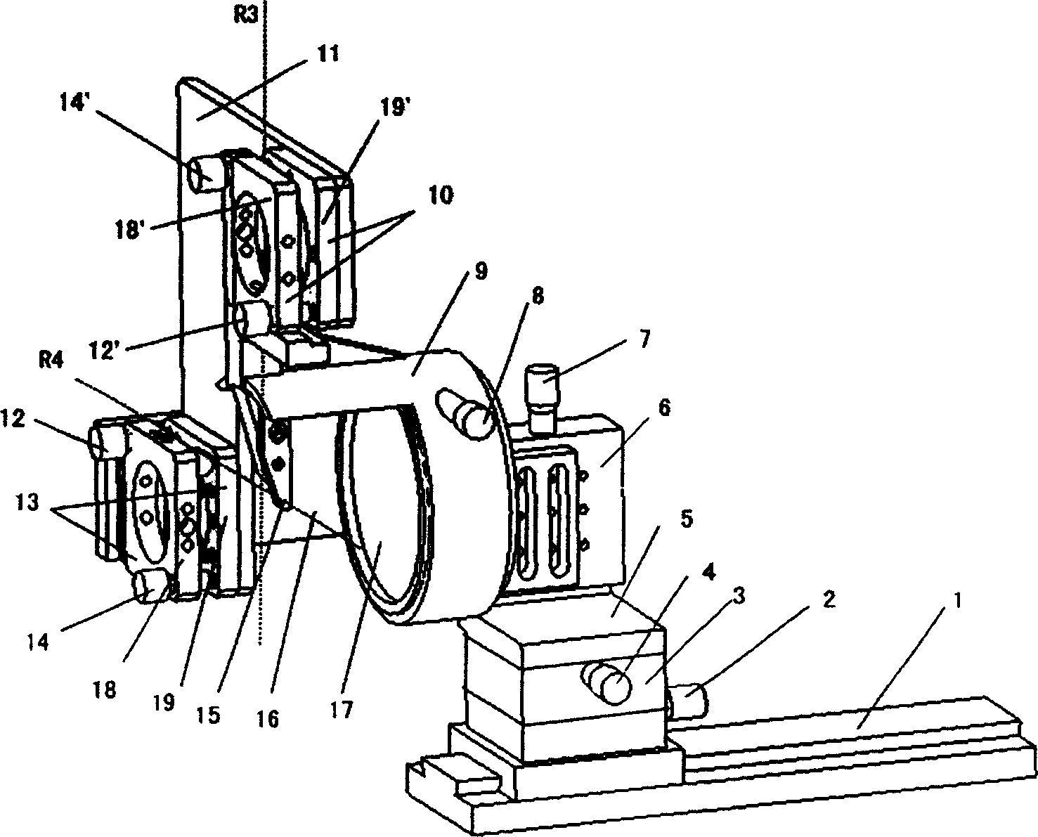
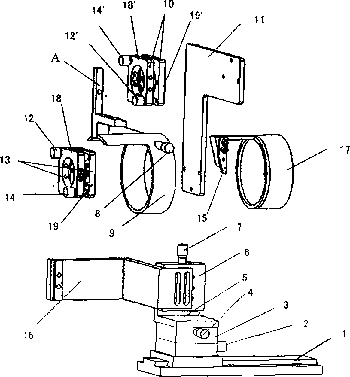
[0018] In the micromirror array type high-port optical switch, the beam alignment of the fiber collimator array becomes a key process link in the device manufacturing. After alignment, the optical signal output from any port of the input collimator array is required The mirror can be coupled into the exit collimator array after reflection. The optical alignment of the array mainly includes the following processes (such as Figure 4 shown):
[0019] 1. Make a collimator array, such as Figure 4 I or II in , so that the outgoing beams are equally spaced and parallel;
[0020] 2. Fix I, clamp A' in II in the fastening clip of the adjustment device, and align the A and A' ports in the two collimator arrays of collimator array I and II;
[0021] 3. Without changing the position of the collimator array I, rotate and adjust the collimator array II with the light beam of A' as the axis, so that the insertion loss values of all ports can be minimized.
[0022] It can be seen from...
PUM
 Abstract
Description
Claims
Application Information