
Method for making metal die part for plate-processing machine tool

A technology for metal mold and sheet metal processing, which is applied in the field of metal mold parts for manufacturing machine tools for sheet metal processing, and can solve the problems of long time, time-consuming, and inability to fully and effectively exert the production potential of the manufacturing plant.

Inactive Publication Date: 2004-12-01
AMADA CO LTD
View PDF1 Cites 4 Cited by
  • Summary
  • Abstract
  • Description
  • Claims
  • Application Information

AI Technical Summary

Problems solved by technology

Therefore, in this way, it takes a long time for the user to commission the valuation and get the result
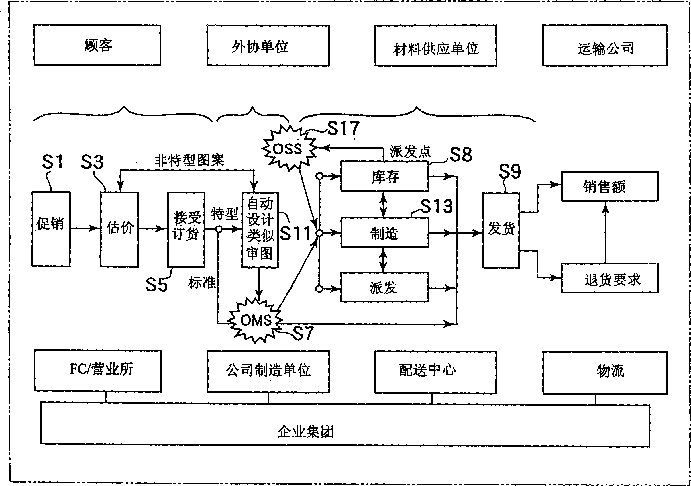
[0008] In addition, even if the salesperson accepts the user's order and brings the accepted order back to the company, and the company's order-handling personnel handle the order formalities in order to formally confirm the order for the first time, correspondingly, the order arrives at the design and manufacturing departments later
[0009] In addition, because other products except standard products are designed by the design department, it takes time from receiving an order to completing the design, and correspondingly, the order reaches the manufacturing department even later.
[0010] In addition, for the manufacturing department, since the best manufacturer cannot be selected from several workshops or outsourcing units of the manufacturing plant to issue corresponding manufacturing instructions in a timely manner, the production potential of the manufacturing plant cannot be fully and effectively utilized. Therefore, Additional time is required until the item is finished
[0011] Furthermore, for the delivery department, since the weight, region, and delivery time of the product cannot be considered comprehensively to determine the carrier, it will take extra time until the user receives the product.

Method used


Image

  • Method for making metal die part for plate-processing machine tool
  • Method for making metal die part for plate-processing machine tool
  • Method for making metal die part for plate-processing machine tool

Examples


Embodiment Construction

[0088] Embodiments of the sales support system and the method of manufacturing metal mold parts of a machine tool for sheet metal processing according to the present invention will be described below with reference to the drawings.

[0089] The sales support system of this embodiment is a sales support system for selling tools as commodities or products. (These tools are especially punches and dies of turret punch presses or punches and dies of plate bending machines, etc.).

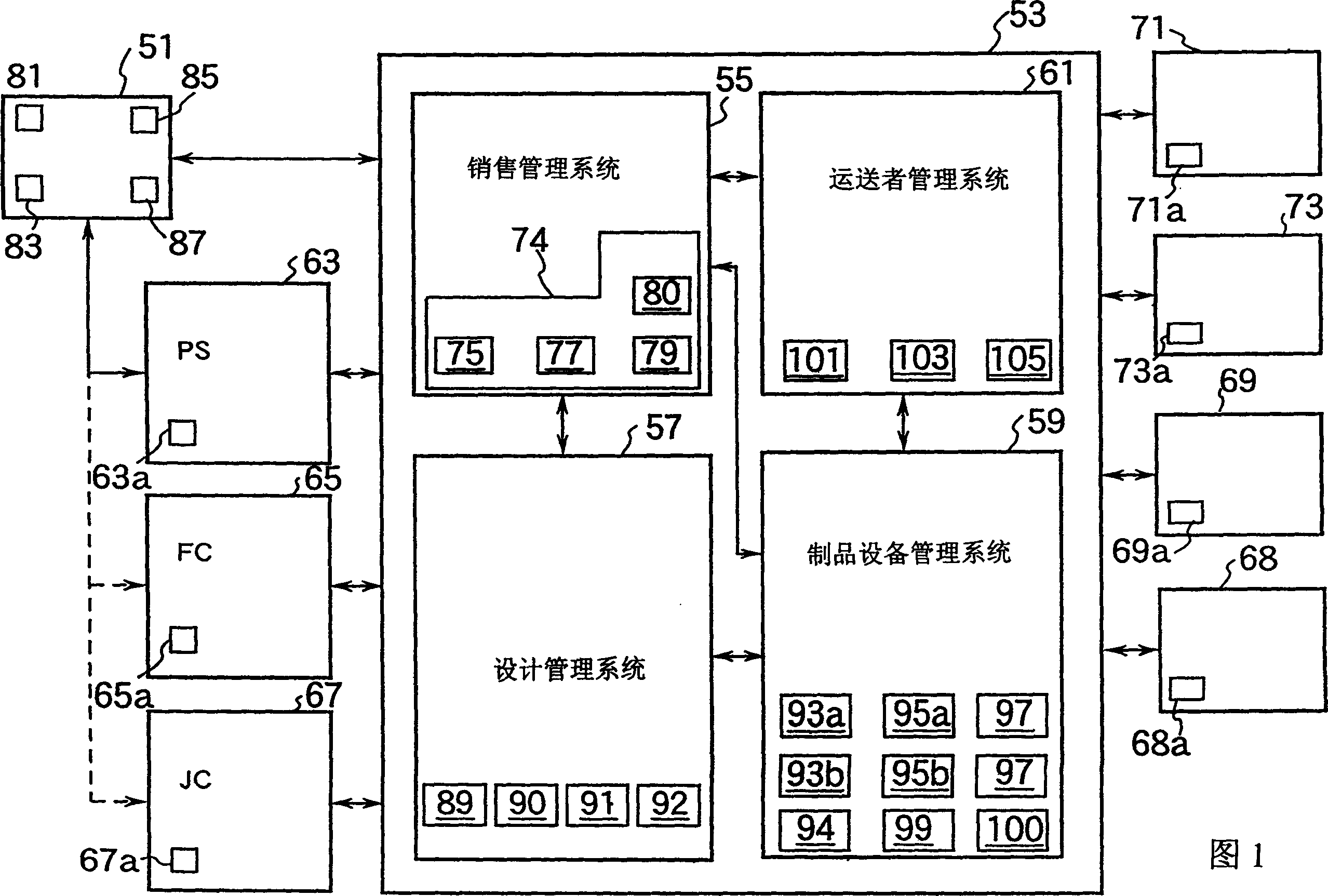
[0090] Fig. 1 is a block diagram showing the outline of this embodiment.

[0091] As shown in FIG. 1, this sales support system has a terminal system 51 equipped with an input device 81 for inputting product-related information desired by customers and a display device 83 for displaying product-related information to customers. Here, the product information required by the customer includes a purchase order for the product.

[0092] In addition, the sales system includes an information management syste...


PUM


Abstract

To easily know residual amount of a wire by providing a residual amount mark of the wire on a rotary disc of a packing device of the wire which is constituted to draw the wire in a bundle which is mounted on the rotary disc from a side surface part of an outer packaging case. Within an outer packaging case 10, a bottom plate 20 is stored. Next, a ring-shaped sliding member 30 is arranged at the outer peripheral location of a fixed core material 21 of the bottom plate 20 and a rotary core material 40 is arranged on the sliding member 30. Next, a rotary disc 50 provided with a residual amount mark 502 on the upper surface of a lower part 41 of the rotary core material 40 is arranged. At this time, a state that the rotary core material 40 is inserted / passed into / through an octagonal hole 51 at the center part of the rotary disc 50 is made. The rotary disc 50 is provided with a residual amount mark 502 which preliminarily shows residual amount of a wire 60 in a bundle. By reading this residual amount mark 502 from a window for drawing wire 11 on the side surface of the outer packaging case 10, residual amount of the wire 60 in a bundle, that is, a residual amount length, for instance, can be easily confirmed.

Description

[0001] This application is a divisional application of the invention application with the application number 99815139.4 and the application date of October 27, 1999, and the title is "Sales Support System". technical field [0002] The invention relates to the field of mechanical manufacturing, and more specifically relates to a method for manufacturing metal mold parts of a machine tool for sheet metal processing. Background technique [0003] Usually in machine tools such as metal processing machinery, for example, metal parts such as molds, punches, and guide rails used in punch presses will be renewed due to wear and tear. have to be replaced. [0004] In addition, the users of machine tools need some new parts and tools according to the different products to be processed. At this time, a certain delivery date is usually stipulated in the above-mentioned processed products. Therefore, the user always wishes to obtain these novel parts and tools in the shortest possible...

Claims


Application Information

Patent Timeline
Patent Type & Authority Applications(China)
IPC IPC(8): G06Q10/00G06Q30/00
CPCG06Q10/08G06Q30/0635G06Q30/0623G06Q10/087G06Q30/0621G06Q30/06
Inventor 田村俊雄浅羽整尾登善则西冈昌弘福井幸夫长井笃本田清利
Owner AMADA CO LTD
Learn More