Differential cloth-feed sewing machine

A sewing machine and cloth feeding technology, applied in the direction of cloth feeding mechanism, sewing machine components, program-controlled sewing machines, etc., can solve the problems of lowering sewing quality, lowering productivity, and difficulty in feeding the cloth feeding section, etc., so as to improve sewing quality effect

Active Publication Date: 2004-12-01
JUKI CORP
View PDF0 Cites 9 Cited by
  • Summary
  • Abstract
  • Description
  • Claims
  • Application Information

AI Technical Summary

Problems solved by technology

[0006] However, since the former differential feed sewing machine uses a single drive motor to drive the two top feed parts, it is difficult to adjust the feed amount of the two top feed parts separately.
That is, the structure of its power transmission mechanism, for example, by using gears with different outer diameters or belt pulleys, it is possible to drive each upper feeding part with different feeding amounts, but it is necessary to replace the gears, etc.
[0007] Therefore, when sewing the upper sleeves, when sewing the ends of the two pieces of fabric, it is difficult to operate, and there is a problem that the productivity is reduced or the reject rate is high.
[0008] In addition, since the differential feed sewing machine described in Patent Document 1 is driven by a different drive motor for each top feed portion, it is possible to set the feed amount separately, but this differential feed sewing machine cannot During sewing, the upper feed amount is changed for each of the multiple sewing sections to sew
Therefore, the amount of shirring cannot be changed while the selvedges of the two pieces of fabric are being sewn together.
In addition, when the curvature of the curve at the end of the fabric changes midway, it is difficult to fully follow the curve, reducing the sewing quality.
[0009] In addition, because on this sewing machine, the upper feeding part moves up and down while feeding the cloth, and because the upper feeding part is completely separated from the fabric during the sewing machine sewing one stitch, or the needle penetrates The cloth cannot be fed during the period of the cloth, so the cloth cannot be fed correctly, and the sewing quality is reduced

Method used


Image

  • Differential cloth-feed sewing machine
  • Differential cloth-feed sewing machine
  • Differential cloth-feed sewing machine

Examples


Embodiment Construction

[0053] (Overall structure of the embodiment)

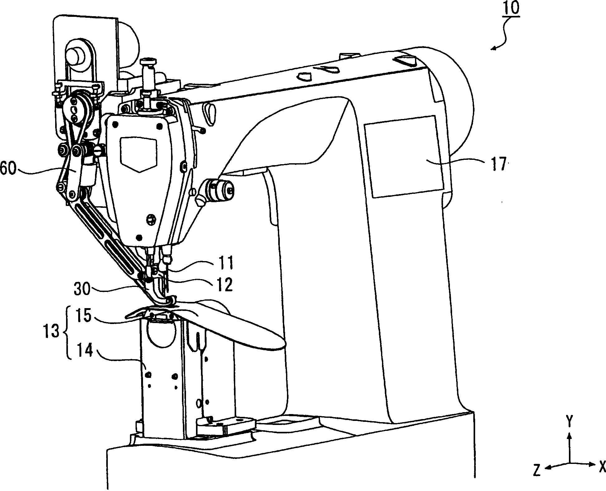
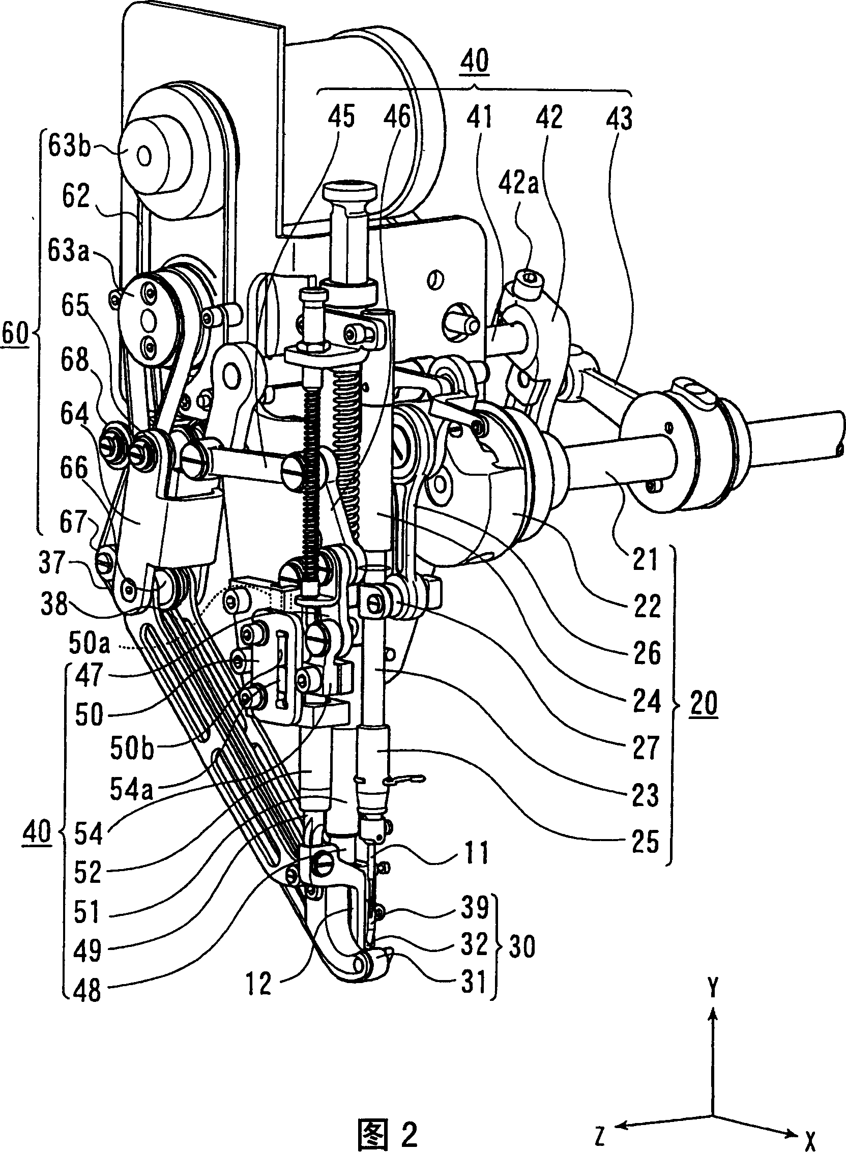
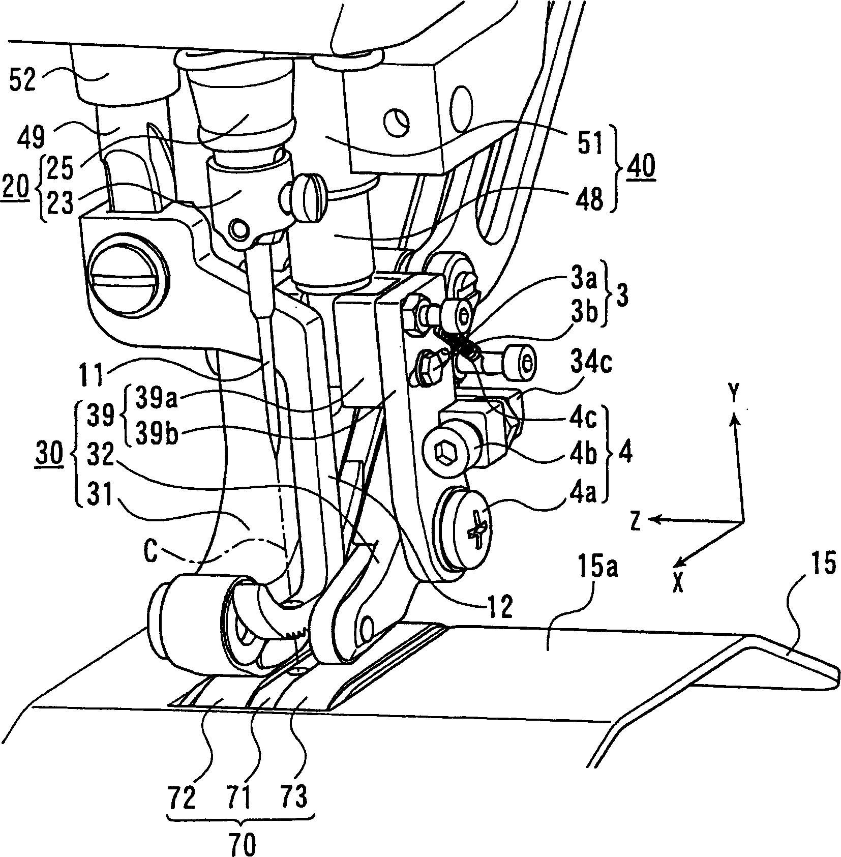
[0054] Refer now figure 1 ~ Figure 27 illustrates an embodiment of the present invention. The differential feed sewing machine 10 of this embodiment is a sewing machine that uses a method of setting a difference in the respective feed speeds of the upper and lower cloths to be sewn while folding and sewing. For example, it is used for sleeves and Sewing of large front and rear body, etc.

[0055] In addition, the so-called shirring means that there is a difference in the width of the sewing pitch between the upper cloth and the lower cloth, and increasing the difference (the shirring amount) can make the seam stretchable. Therefore, when sewing the sleeves and the front and back of the body, the amount of stitching on the shoulder side is increased so that it is larger than the underarm side, so that the shoulder side that requires stretchability after sewing can have a margin.

[0056] Here, the direction of the up and down movement...


PUM


Abstract

The invention provides a differential feeding sewing machine, the operability of which is improved during sewing. An upper feeder has a first upper feeding section 31 feeding an upper fabric in the vicinity of a sewing needle 11, a second upper feeding section 32 adjoining the first upper feeding section 31 along the direction of intersecting the feeding direction and feeding the upper fabric and a driving means capable of controlling individually the amount of feed. A lower feeder has a lower feeding section 70 feeding a lower fabric and a driving means therefor and has an action control means 80 controlling the action of each driving means on the basis of a setting input to determine the amount of feed of the first upper feeding section and the second upper feeding section and the lower feeding section, respectively for each of a plurality of sewing sections changed during sewing.

Description

Technical field [0001] The present invention relates to a differential feeding sewing machine that performs sewing while changing the upper feeding amount relative to the lower feeding amount. Background technique [0002] As the above-mentioned differential feed sewing machine, a differential feed sewing machine model 550-16-26 manufactured by DIUKOPUARDOLA is known. This differential feeding sewing machine has: the first and second upper cloth feeding parts arranged above the needle plate and feeding the upper cloth, the lower cloth feeding part conveying the lower cloth on the needle plate from below, and a single drive A motor driving mechanism for driving the first and second upper cloth feeding parts, and a driving mechanism for driving the lower cloth feeding part with one driving motor. [0003] In addition, as another differential feed sewing machine, it is well known that it has first and second upper feed parts that sandwich the needle drop position and feed the cloth ...

Claims


Application Information

Patent Timeline
Patent Type & Authority Applications(China)
IPC IPC(8): D05B19/16D05B27/02D05B27/08D05B27/16
CPCD05B27/16D05B19/16
Inventor 镰仓新治野村绍雄
Owner JUKI CORP
Why Eureka
Try Eureka