Motor driving apparatus
A technology of motor drive and motor, applied in the field of motor drive device, can solve the problems of increasing the shape of linear vibration motor, reducing the reliability of the drive device, increasing the cost, etc.
- Summary
- Abstract
- Description
- Claims
- Application Information
AI Technical Summary
Problems solved by technology
Method used
Image
Examples
Embodiment 1
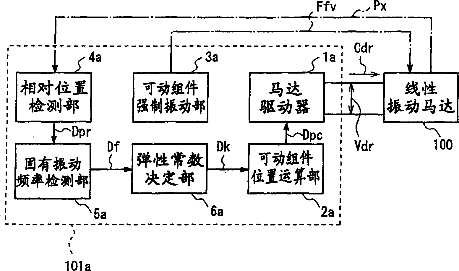
[0161] figure 1 It is a block diagram illustrating the motor drive device according to Embodiment 1 of the present invention.
[0162]The motor drive device 101a of the first embodiment has two operation modes for operating the linear vibration motor. One operation mode is an operation mode in which the linear vibration motor 100 is driven with a driving voltage or a driving current corresponding to a required motor output to operate a load connected to the linear vibration motor 100 . In this operation mode, the motor driver 101a calculates the position of the movable element of the linear vibration motor based on the driving voltage and the driving current while operating the above-mentioned load, and controls the drive of the linear vibration motor based on the calculated position of the movable element. . Still another operation mode is an operation mode in which the movable unit of the linear vibration motor 100 is allowed to vibrate freely, and the elastic constant k ...
Embodiment 2
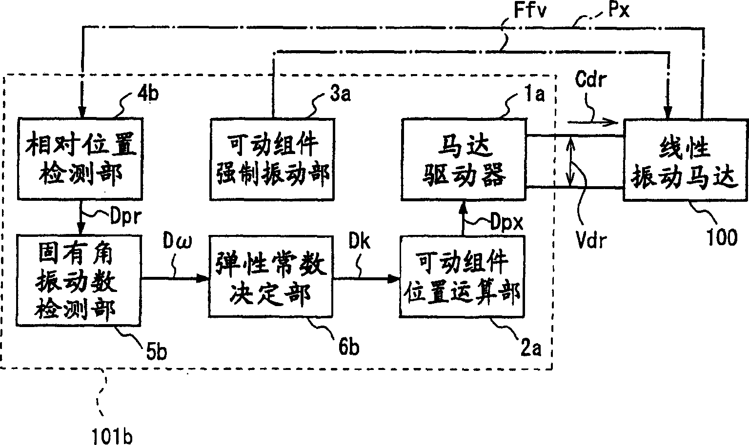
[0207] figure 2 It is a block diagram illustrating the motor drive device 101b of the second embodiment of the present invention.
[0208] The motor drive device 101b of the second embodiment differs from the motor drive device 101a of the first embodiment only in that the elastic constant k in the position calculation for calculating the position of the movable member is calculated from the natural angular vibration number ω of the movable member. different.
[0209] That is, the motor drive device 101b of the second embodiment replaces the natural frequency detection unit 5a of the motor drive device 101a of the first embodiment, and has a detection function based on the timing when the freely vibrating movable member passes a certain fixed point (relative position). The natural angular vibration number detection unit 5b of the natural angular vibration number (natural angular velocity) ω of the moving assembly replaces the elastic constant determination unit 6a of the mot...
Embodiment 3
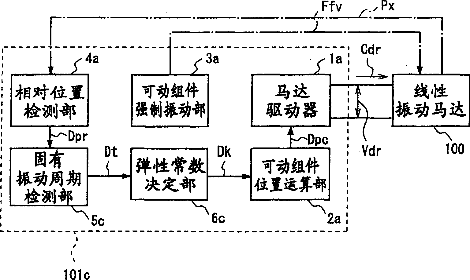
[0243] image 3 is a block diagram illustrating a motor drive device according to a third embodiment of the present invention.
[0244] The motor drive device 101c of the third embodiment differs from the motor drive device 101a of the first embodiment only in that the elastic constant k in the position calculation for calculating the position of the movable member is calculated from the natural vibration period T of the movable member. .
[0245] That is, the motor drive device 101c of the third embodiment replaces the natural frequency detection unit 5a of the motor drive device 101a of the first embodiment, and has a detection function based on the timing when the freely vibrating movable member passes a certain fixed point (relative position). The natural vibration period detection part 5c of the natural vibration period T of the moving assembly replaces the elastic constant determination part 6a of the motor drive device 101a of Embodiment 1, and has an elastic constant ...
PUM
 Abstract
Description
Claims
Application Information
 - R&D
- Intellectual Property
- Life Sciences
- Materials
- Tech Scout
- Unparalleled Data Quality
- Higher Quality Content
- 60% Fewer Hallucinations
Browse by: Latest US Patents, China's latest patents, Technical Efficacy Thesaurus, Application Domain, Technology Topic, Popular Technical Reports.
© 2025 PatSnap. All rights reserved.Legal|Privacy policy|Modern Slavery Act Transparency Statement|Sitemap|About US| Contact US: help@patsnap.com


