Nverter circuit for discharge lamps for multi-lamp lighting and surface light source system

A technology of an inverter and a discharge tube, which is applied in the field of an inverter circuit for a discharge tube and a surface light source system, can solve the problems of influence, increase of steady-state discharge current, uneven current of cold cathode tube, etc., so as to reduce parasitic capacitance, The effect of increasing the self-resonant frequency, high shunt/equalization effect

Inactive Publication Date: 2004-12-01
牛岛昌和 +1
View PDF8 Cites 5 Cited by
  • Summary
  • Abstract
  • Description
  • Claims
  • Application Information

AI Technical Summary

Problems solved by technology

[0067] Secondly, in the cold-cathode tube, the steady-state discharge voltage is extremely high, which greatly affects the parasitic capacitance generated around the cold-cathode tube and the wiring before it, so from the inverter circuit to between the cold-cathode tube When the parasitic capacitance generated by the wiring is different, the current of the cold cathode tube is uneven and appears

Method used


Image

  • Nverter circuit for discharge lamps for multi-lamp lighting and surface light source system
  • Nverter circuit for discharge lamps for multi-lamp lighting and surface light source system
  • Nverter circuit for discharge lamps for multi-lamp lighting and surface light source system

Examples


Embodiment Construction

[0111] Below, such as Figures 1 to 15 As shown, the embodiment of the discharge tube inverter circuit and the surface light source system for multi-lamp lighting of the present invention will be described in detail.

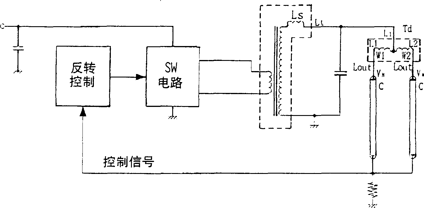
[0112] figure 1 is a generalized embodiment showing the principles of the invention, the secondary side of the leakage magnetic flux transformer Ls of the step-up transformer of the inverter circuit for the discharge tube is provided with two windings W 1 and W 2 The coil L 1 and L 2 , each coil L 1 and L 2 The opposite ends Li are connected together and connected to the secondary winding L of the leakage magnetic flux transformer Ls t , each coil L 1 and L 2 the other end of L out are each connected to the high voltage terminal V of the cold cathode tube C H side.

[0113] Connect each coil L 1 and L 2 , so that each of the aforementioned coils L 1 and L 2 The generated magnetic flux is in the opposite state, and to increase the coupling factor ...


PUM


Abstract

Inverter circuit for discharge tube for multi-lamp lighting and surface light source system. To obtain a small and high performance shunt characteristic by eliminating a setting of an excess reactance by controlling the value of the negative resistance characteristics of a fluorescent tube to give a shunt transformer a reactance higher than the negative resistance characteristics. Two coils are connected to a secondary winding of the set-up transformer of the inverter circuit of a discharge tube. The two coils form a shunt transformer of a current, in which magnetic fluxes generated in the two coils are faced each other and the fluxes are magnetically combined as to be canceled. A discharge tube is connected to each of the two coils. The tube currents of each of the discharge tubes are balanced in the inverter circuit for the discharge tube. Lighting is performed when a reactance at the the inverter circuit operation frequency of the inductance relating to the balance of the shunt transformer exceeds the negative resistance of the discharge tube.

Description

technical field [0001] The invention relates to an inverter circuit and surface light source system for a discharge tube with multi-lamp lighting, in particular to an inverter circuit for a discharge tube such as a cold cathode fluorescent tube lights up the current balancing transformer. Background technique [0002] In recent years, the size of the backlight system for liquid crystals has continued to increase. With this development, many cold-cathode tubes are used in one backlight system. For this reason, the inverter circuit for liquid crystal backlight systems uses a device for lighting up many cold-cathode tubes. Multi-lamp lighting circuit. [0003] So far, in order to light up most cold cathode tubes, such as Figure 16 As shown, use one or more step-up transformers for large power, with most capacitive ballasts as the intermediary, and connect each cold cathode tube to the secondary side output of the step-up transformer, so as to output the secondary side of the ...

Claims


Application Information

Patent Timeline
Patent Type & Authority Applications(China)
IPC IPC(8): F21V23/02F21S2/00F21S8/04F21Y103/00H01F38/08H05B41/24H05B41/26H05B41/282
CPCH05B41/2822H01F38/10H01F30/04H05B41/26
Inventor 川本幸治牛岛昌和山本阳一木岛稔
Owner 牛岛昌和
Why Eureka
Try Eureka