

Mechanical driving structure of artificial intelligent insulin pump
An insulin pump and artificial intelligence technology, applied in the direction of subcutaneous injection devices, etc., can solve problems such as uncompactness, long dressing change time, and reduced safety factor, and achieve the effect of simple and easy operation, convenient and practical operation, and simple structure
- Summary
- Abstract
- Description
- Claims
- Application Information
AI Technical Summary
Problems solved by technology
Method used
Image

Examples
Embodiment Construction
[0022] The present invention will be further described in detail below in conjunction with the accompanying drawings.
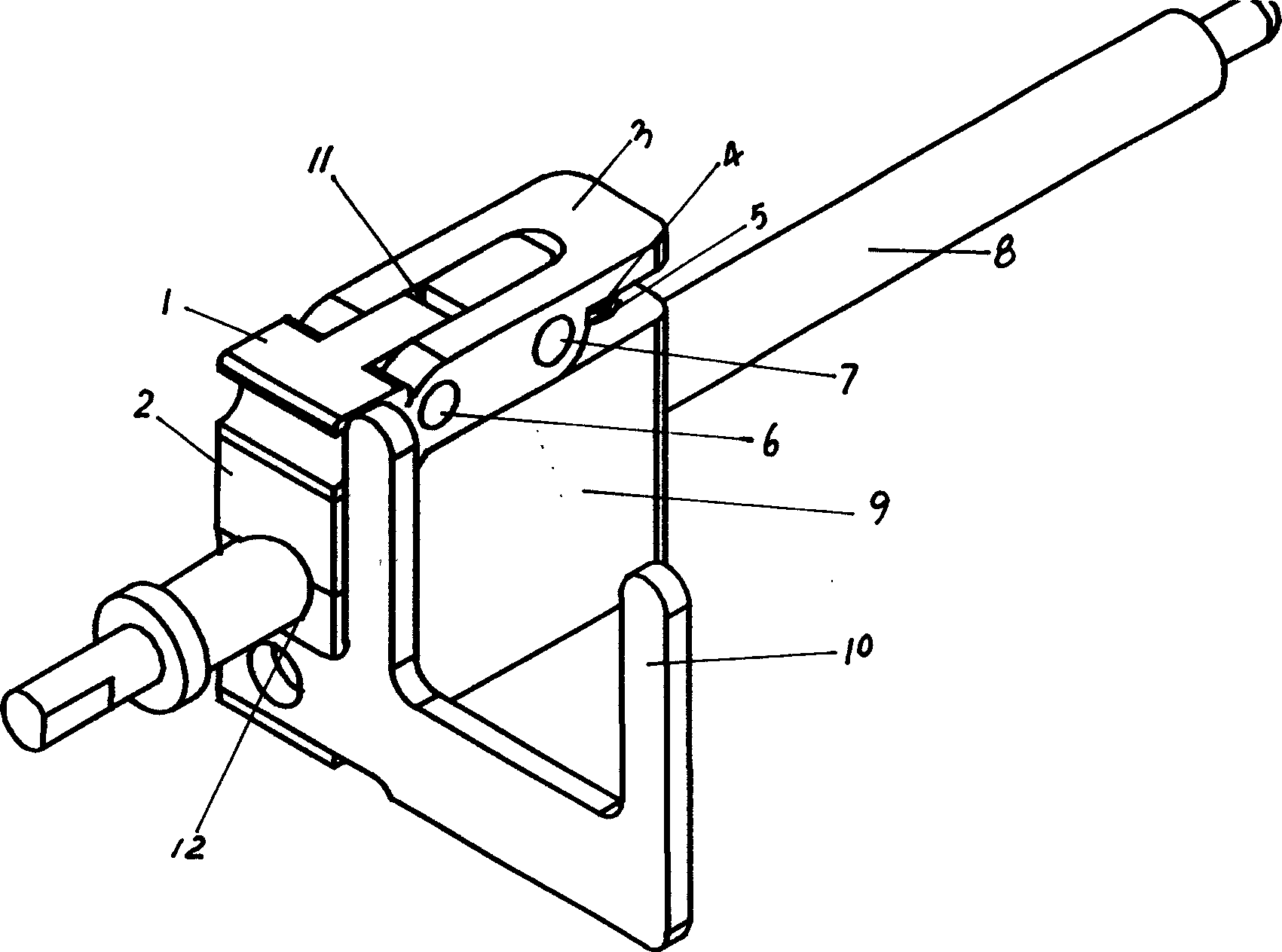
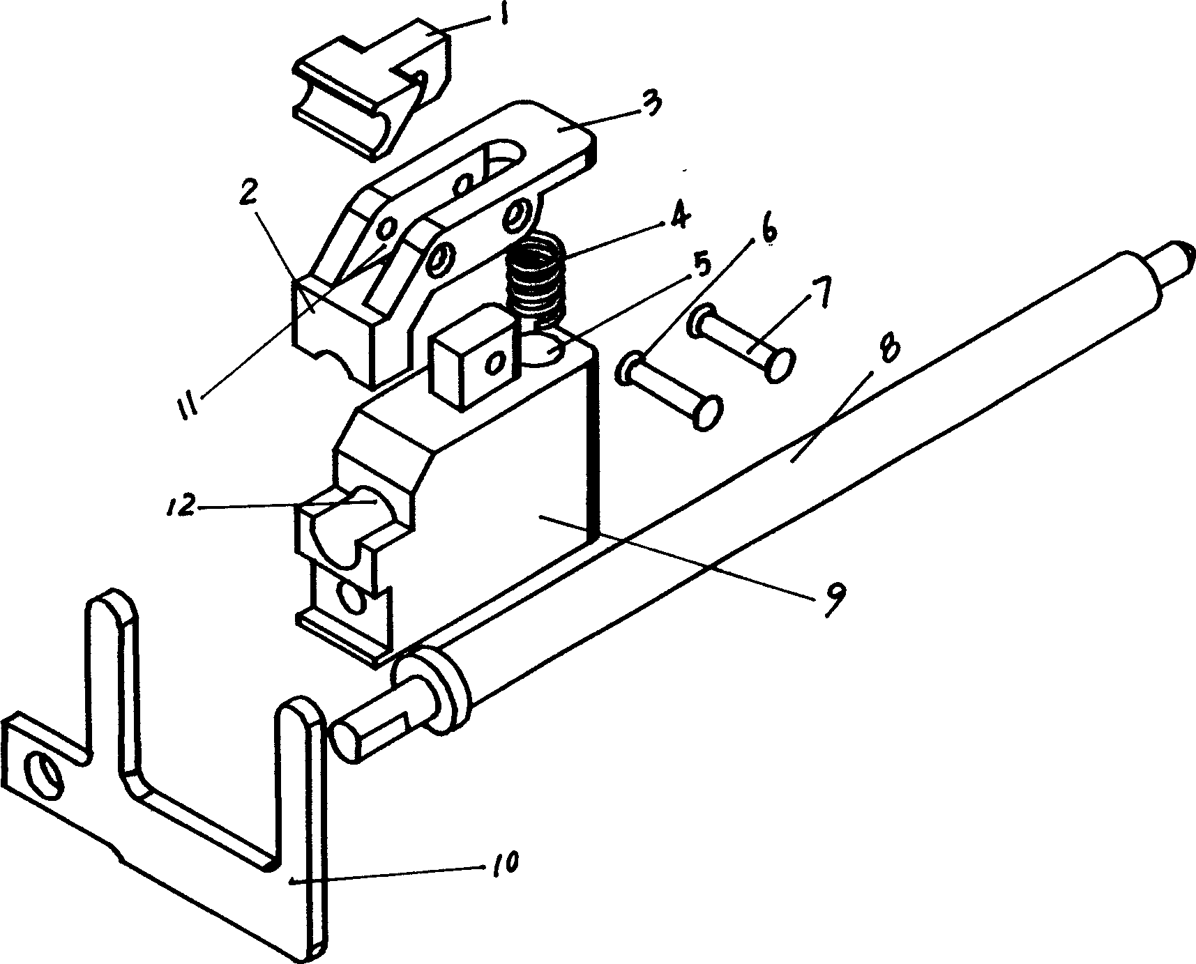
[0023] Such as figure 1 and figure 2 As shown, the mechanical transmission structure of the artificial intelligence insulin pump of the present invention includes a trigger block 1, a half nut 2, a moving block 9, a push plate 10, a screw rod 8, a spring 4, a pin shaft 6 and a fulcrum pin shaft 7, and a half nut 2 There is a tilting arm 3 extended, and the moving block 9 is provided with a circular groove 5 and a guide hole 12. The tilting arm 3 is provided with an embedded groove 11, and the guide hole 12 is matched with the screw rod 8, and the screw rod 8 passes through the guide hole 12. However, the threaded end of the half nut 2 is disposed at the end of the guide hole 12 . The wrench 1 is connected with the half nut 2 through the pin 6, that is, the wrench 1 and the tilting arm 3 are nested and connected in the embedded groove 11 through the pin 6; ...
PUM
 Abstract
Description
Claims
Application Information