

Charged detection method for insulator of high voltage direct current transmission line
A high-voltage direct current, transmission line technology, applied in the direction of measuring current/voltage, measuring electricity, measuring devices, etc., can solve the problems of no live detection, inability to see internal defects and hidden defects of insulators, and inability to use them
Inactive Publication Date: 2004-12-29
NORTH CHINA ELECTRIC POWER UNIV (BAODING)
View PDF0 Cites 16 Cited by
- Summary
- Abstract
- Description
- Claims
- Application Information
AI Technical Summary
Problems solved by technology
[0002] At present, the common way to detect composite insulators of HVDC transmission lines is visual inspection with high-powered telescopes. This method cannot see internal defects and hidden defects of insulators.
In a very few areas, infrared imagers are used to detect insulators based on temperature changes, but they cannot be used under strong background light during the day, and the cost is also expensive
For the low-zero value suspension insulators of HVDC transmission lines, there is currently no live detection method
Method used
View moreImage
Smart ImageViewing Examples

Examples
Embodiment
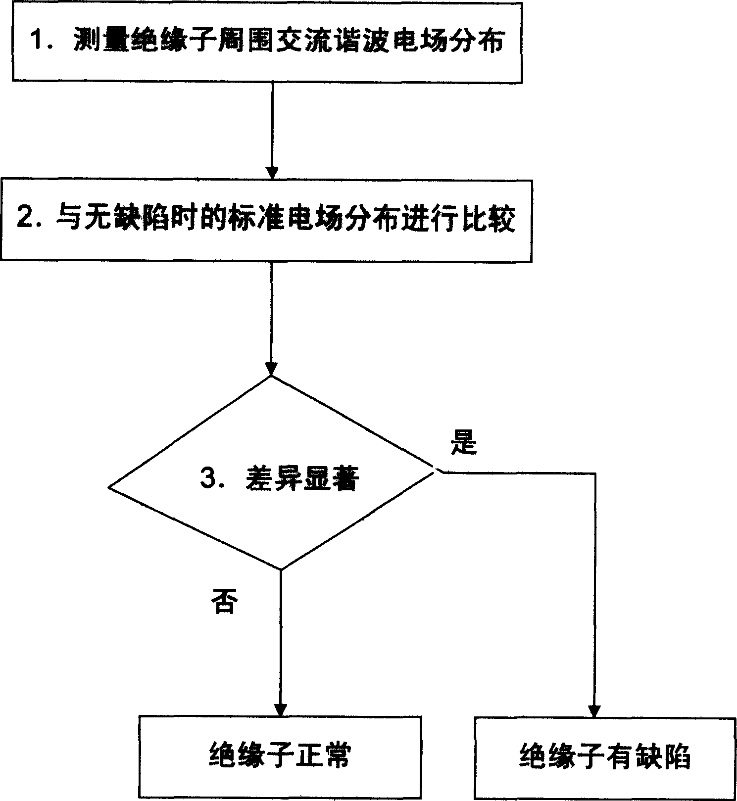
[0010] Embodiment: Referring to the accompanying drawings, a method for live detection of high-voltage direct current transmission line insulators, the steps are:
[0011] (1) Detect the distribution of AC harmonic electric field around the insulator;
[0012] (2) Compare with the standard electric field distribution when there is no defect;
[0013] (3) If there is no significant difference between the two distributions, the insulator is judged to be normal, otherwise it is judged to be defective.
Login to View More PUM
 Abstract
The present invention belongs to the field of electric power transmission, and is especially live detection method of synthetic insulator fault and zero value insulator in high voltage DC power transmission line. The detection method includes the steps of: detecting the AC harmonic electric field distribution around the insulator; comparing with standard electric field distribution; and judging whether the insulator is normal or in fault based on whether to have obvious difference between the two distributions. The present invention facilitates the detection of insulator in high voltage DC power transmission line with voltage level as high as 500 KV and has relatively high sensitivity.
Description
technical field [0001] The invention belongs to the field of electric power transmission, and in particular relates to a method for live detection of synthetic insulator defects and zero-value insulators of high-voltage direct current transmission lines. Background technique [0002] At present, the common way to detect composite insulators of HVDC transmission lines is visual inspection with high-powered telescopes. This method cannot see internal defects and hidden defects of insulators. In a very few areas, infrared imagers are used to detect insulators based on temperature changes, but they cannot be used under strong background light during the day, and the cost is also expensive. As for the low-zero value suspension insulators of HVDC transmission lines, there is currently no live detection method. Contents of the invention [0003] The purpose of the present invention is to provide a high-sensitivity, easy-to-use live detection method for defects of high-voltage di...
Claims
Login to View More Application Information
Patent Timeline
 IPC IPC(8): G01R19/00G01R31/02G01R31/08
Inventor程养春李成榕王景春王伟丁立健屠幼萍
OwnerNORTH CHINA ELECTRIC POWER UNIV (BAODING)