Backlight system and method for controlling the same

A technology of backlight system and control method, applied in optics, nonlinear optics, instruments, etc., can solve the problems of increased cost and high price

Inactive Publication Date: 2004-12-29
AU OPTRONICS CORP
View PDF2 Cites 18 Cited by
  • Summary
  • Abstract
  • Description
  • Claims
  • Application Information

AI Technical Summary

Problems solved by technology

However, the price of a special photodetector with the function of measurin

Method used


Image

  • Backlight system and method for controlling the same
  • Backlight system and method for controlling the same
  • Backlight system and method for controlling the same

Examples


Embodiment Construction

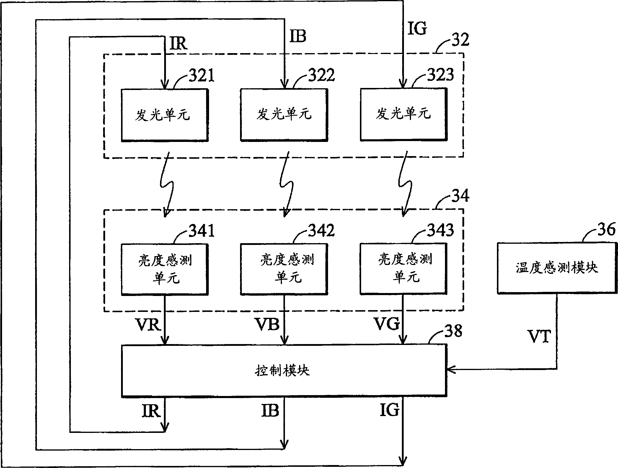
[0035] image 3 A block diagram of the backlight system of the present invention is shown. As shown in the figure, the backlight system includes: a light emitting module 32 , a brightness sensing module 34 , a temperature sensing module 36 and a control module 38 .

[0036] The light emitting module 32 has light emitting units 321 - 323 , and the light emitting units 321 - 323 emit light according to corresponding driving signals IR, IB, IG. The light-emitting units 321-323 are composed of LED components, and the LED components can be divided into three types, which are red LEDs, blue LEDs and green LEDs. In this embodiment, it is assumed that the light-emitting unit 321 is composed of red LEDs. The light emitting unit 322 is composed of blue LED components and emits light according to the driving signal IB; the light emitting unit 323 is composed of green LED components and emits light according to the driving signal IG.

[0037] The brightness sensing module 34 has brightn...


PUM


Abstract

The present invention is back light system and its control method. The brightness signal of the light emitting module in the back light system is compared with preset brightness signal, and is regulated based on the comparison result to make the brightness signal of the light emitting module equal to the preset brightness signal. Where, the preset brightness signal changes with the temperature of the light emitting module to limit the back light brightness and the chroma within some stable range.

Description

technical field [0001] The present invention relates to a backlight system and a control method thereof, in particular to a backlight system composed of light emitting diodes (Light Emitting Diode; LED) and a control method thereof. Background technique [0002] With the improvement and improvement of the display manufacturing technology, the liquid crystal display (Liquid Crystal Display, LCD) with the characteristics of small size and low radiation has gradually replaced the traditional cathode ray tube (Cathode Ray Tube, CRT) display in recent years. [0003] Generally speaking, the backlight module (Back Lighting Module) of the traditional liquid crystal display mostly adopts the cold cathode fluorescent tube (Cold Cathode Fluorescent Lamp, CCFL) as the light source, but because the cold cathode fluorescent tube (CCFL) has the problem that it is difficult to start at low temperature, so A heater needs to be installed in a cold place, and there must be enough idling time ...

Claims


Application Information

Patent Timeline
IPC IPC(8): G02F1/1335G09G3/36
Inventor 刘邦炫陈志光
Owner AU OPTRONICS CORP
Why Eureka
Try Eureka