Remote monitor for elevator
一种远程监视、电梯的技术,应用在电话通信、电气元件、运输和包装等方向,能够解决浪费时间、信赖性问题等问题
- Summary
- Abstract
- Description
- Claims
- Application Information
AI Technical Summary
Problems solved by technology
Method used
Image
Examples
no. 1 Embodiment
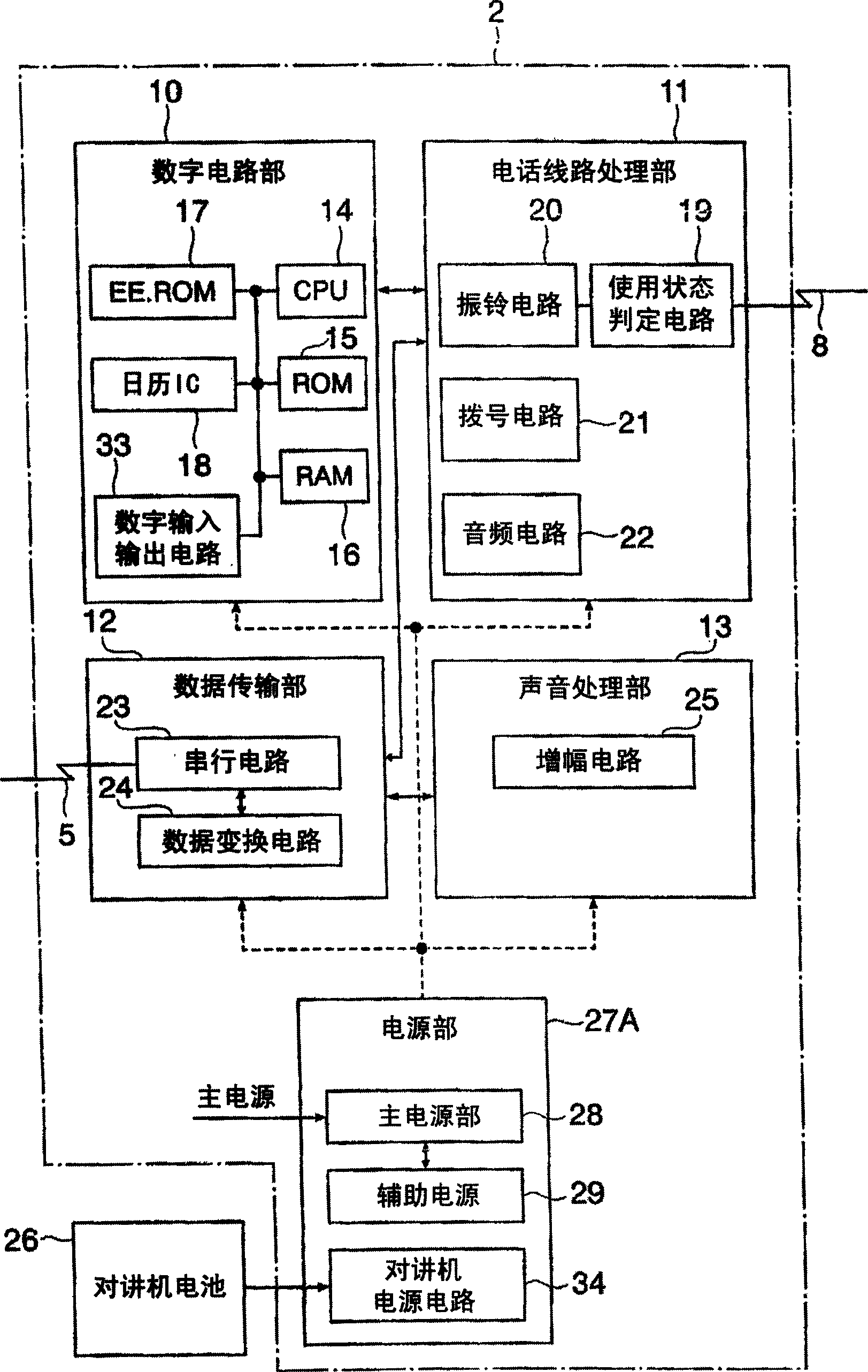
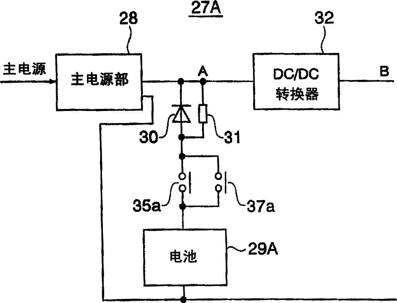
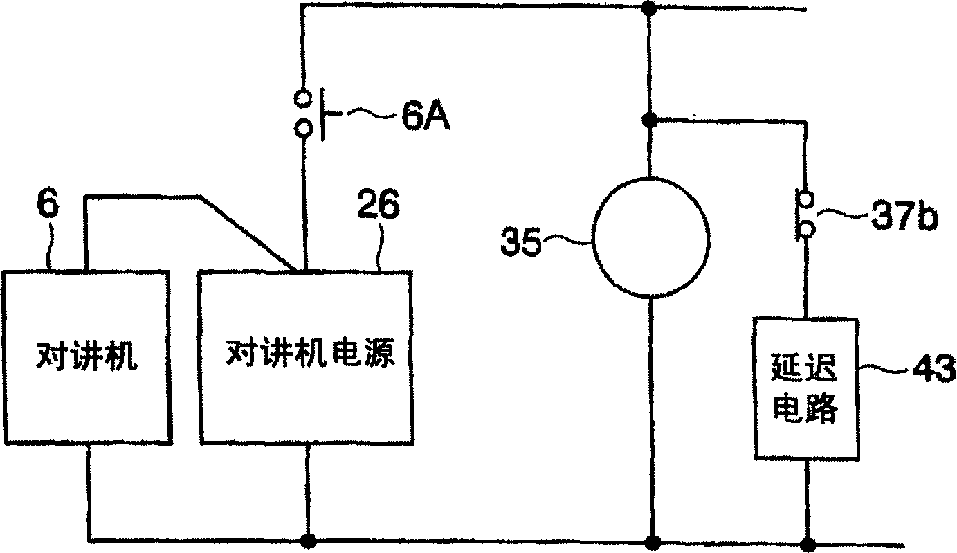
[0070] figure 1 Shown is the block diagram of the first embodiment of the remote monitoring device of the present invention, figure 2 for figure 1 Block diagram of the power supply section of the remote monitoring device, image 3 for figure 1 The block diagram of the walkie-talkie power supply circuit of the remote monitoring device, Figure 4 for figure 1 Block diagram of the digital circuit section of the remote monitoring device.
[0071] figure 1 The remote monitoring device 2 with Figure 22 Based on the remote monitoring device 2, the same symbols represent the same components. exist figure 1 In the remote monitoring device 2 of , in order to control the load circuit of the battery 26 of the walkie-talkie, a power supply unit 27A having a power supply circuit 34 for the walkie-talkie is provided. other parts with Figure 22 The remote monitoring device is the same.
[0072] like figure 2 As shown, in the power supply unit 27A, the structure is as fol...
no. 2 Embodiment
[0089] The second embodiment involves image 3 Delay circuit 43 is described. This delay circuit 43 is constituted by, for example, a combination of C·R (capacitance and resistance), for example, a series circuit of both. The delay circuit 43 is charged by the interphone battery 26 only under the condition that the emergency call button 6A is pressed and the electromagnetic relay 37 does not operate.
[0090] According to the signal from the digital input and output circuit 33, the electromagnetic relay 37 is in an inoperative state, and even after the emergency call button 6A is released, it can be the same as the state when the emergency call button 6A is pressed, with the delay circuit 43 as the power supply The electromagnetic relay 35 is excited for a predetermined time by the relay contact 37b, and the contact 35a is closed. The power supply state when the contact 35a is closed is the same as above.
[0091] With this power supply, the CPU 14 starts up, and the electr...
no. 3 Embodiment
[0094] Figure 8 Shown is a block diagram of an intercom power supply circuit 34 according to a third embodiment of the present invention. A voltage detection unit 42 is provided in the power supply circuit 34 of the walkie-talkie, where the output voltage value of the battery 26 of the walkie-talkie is monitored. The monitoring result is sent to the CPU 14 through the data input unit 41 . The voltage detection unit 42 is a device that detects whether the output voltage value of the battery 26 of the walkie-talkie is equal to or higher than a predetermined value, and can be constituted by a commercially available voltage detection IC.
[0095] Figure 9 shown as will Figure 8 The discharge characteristic of the walkie-talkie battery 26 is expressed as a graph of the voltage-time characteristic. Usually, when it is fully charged, it shows a value slightly higher than the rated value Vn, and then it is consumed due to the flow of discharge current, so that the voltage drops...
PUM
 Abstract
Description
Claims
Application Information
 - R&D
- Intellectual Property
- Life Sciences
- Materials
- Tech Scout
- Unparalleled Data Quality
- Higher Quality Content
- 60% Fewer Hallucinations
Browse by: Latest US Patents, China's latest patents, Technical Efficacy Thesaurus, Application Domain, Technology Topic, Popular Technical Reports.
© 2025 PatSnap. All rights reserved.Legal|Privacy policy|Modern Slavery Act Transparency Statement|Sitemap|About US| Contact US: help@patsnap.com


