

Plasma display
A plasma display, grid-like technology, applied in the direction of cold cathode tubes, etc., can solve the problems of high discharge gas discharge voltage, increasing the operating voltage and power consumption of the plasma display 10, etc.
- Summary
- Abstract
- Description
- Claims
- Application Information
AI Technical Summary
Problems solved by technology
Method used
Image

Examples
Embodiment Construction
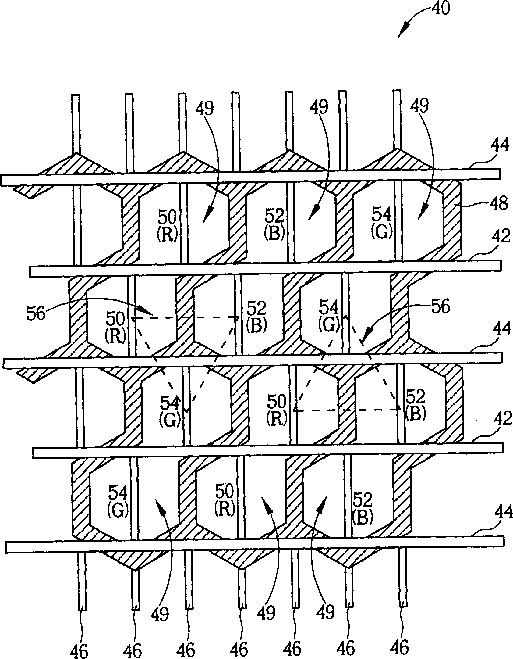
[0051] Please refer to Figure 3 to Figure 5 , Figure 3 to Figure 5 is a top view of the plasma display according to the first embodiment of the present invention, Figure 4 for image 3 A schematic diagram of a closed barrier wall unit is shown. like image 3 As shown, the plasma display 40 includes a front substrate (not shown), a rear substrate (not shown) parallel to and opposite to the front substrate, and a discharge gas (not shown) filled between the front substrate and the rear substrate. In addition, the plasma display 40 also includes a plurality of X electrodes 42, a plurality of Y electrodes 44, and a plurality of address electrodes 46 perpendicular to each X electrode 42 and each Y electrode 44, wherein each X electrode 42 and each Y electrode 44 All of them are arranged in parallel and staggered on the surface of the front substrate, and the address electrodes 46 are arranged in parallel on the surface of the rear substrate. In general, each X electrode 42 ...
PUM
 Abstract
Description
Claims
Application Information