
Plasma display

A plasma display, grid-like technology, applied in the direction of cold cathode tubes, etc., can solve the problems of high discharge voltage of discharge gas, increase of operating voltage and power consumption of plasma display 10, etc.

Inactive Publication Date: 2008-06-18
AU OPTRONICS CORP
View PDF3 Cites 0 Cited by
  • Summary
  • Abstract
  • Description
  • Claims
  • Application Information

AI Technical Summary

Problems solved by technology

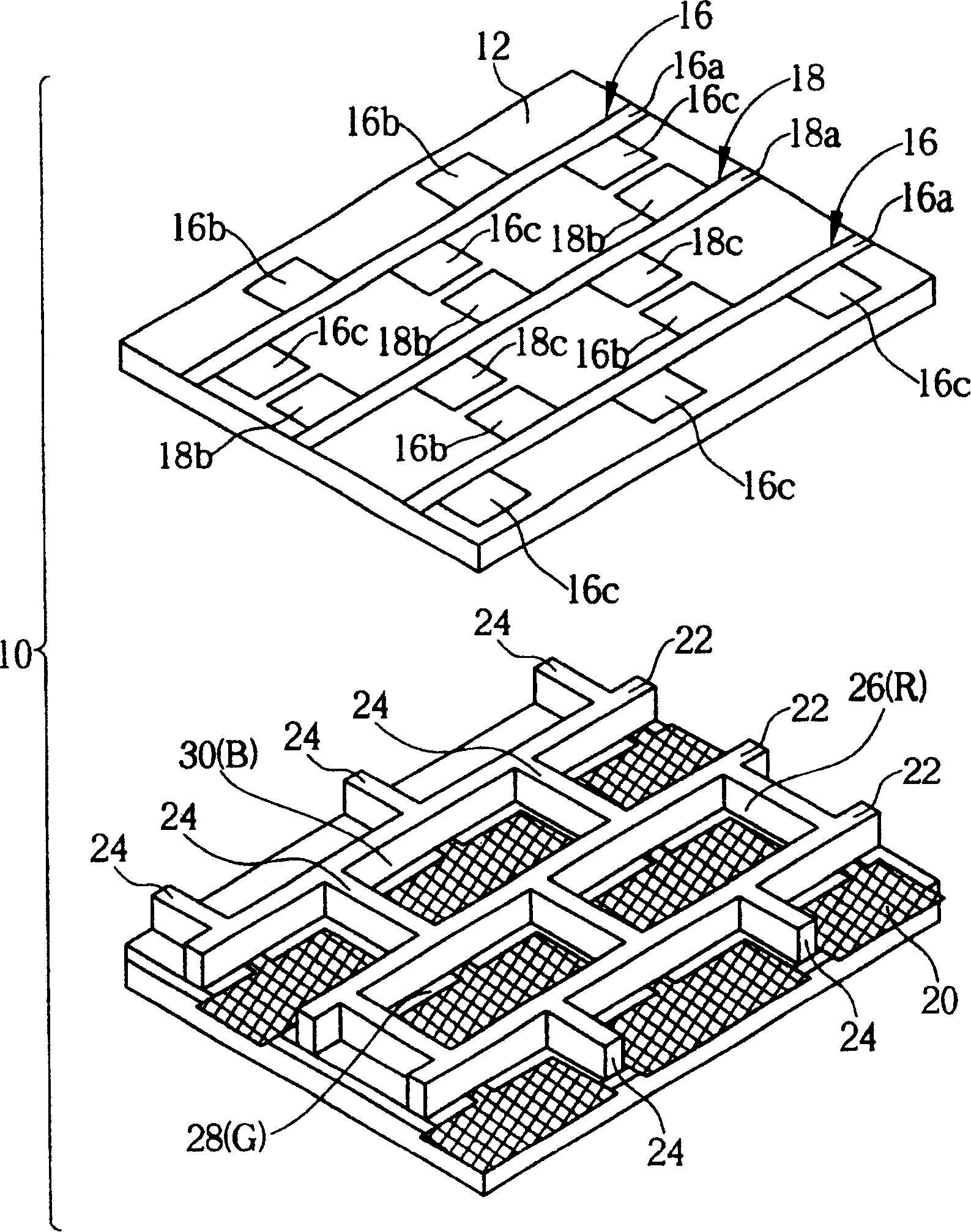
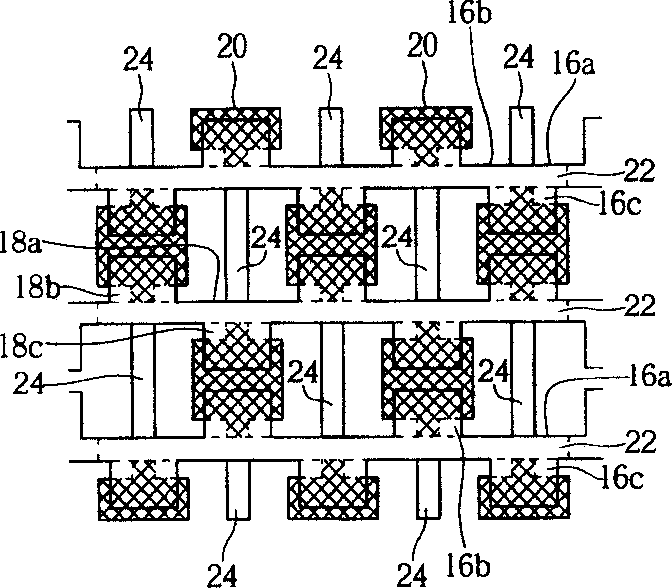
However, in the existing plasma display 10, each sub-pixel unit is defined between the front substrate 12, the rear substrate 14, two adjacent barrier walls 22, and two adjacent barrier walls 24, so each sub-pixel The discharge space of the discharge gas in the unit is limited to the space occupied by each sub-pixel unit. Correspondingly, the discharge voltage of the discharge gas in each sub-pixel unit 26, 28 and 30 is relatively high, thereby increasing the plasma display capacity. 10 Operating voltage and power consumption

Method used


Image

  • Plasma display
  • Plasma display
  • Plasma display

Examples


Embodiment Construction

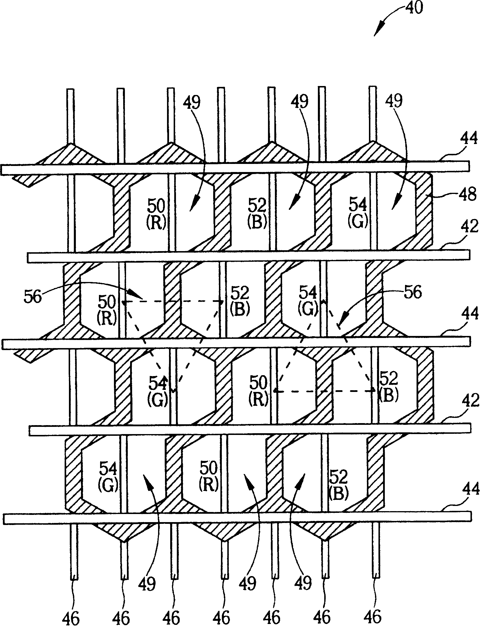
[0051] Please refer to Figure 3 to Figure 5 , Figure 3 to Figure 5 is a top view of the plasma display according to the first embodiment of the present invention, Figure 4 for image 3 A schematic diagram of a closed barrier wall unit is shown. Such as image 3As shown, the plasma display 40 includes a front substrate (not shown), a rear substrate (not shown) parallel to and opposite to the front substrate, and a discharge gas (not shown) filled between the front substrate and the rear substrate. In addition, the plasma display 40 also includes a plurality of X electrodes 42, a plurality of Y electrodes 44, and a plurality of address electrodes 46 perpendicular to each X electrode 42 and each Y electrode 44, wherein each X electrode 42 and each Y electrode 44 All of them are arranged in parallel and staggered on the surface of the front substrate, and the address electrodes 46 are arranged in parallel on the surface of the rear substrate. In general, each X electrode 4...


PUM


Abstract

The invention discloses a plasma display panel, including many first discharge spaces and many sub-pixel units, where the first discharge spaces are arranged between a back plate and a front one and each first discharge space includes at least two sub-pixel units.

Description

technical field [0001] The present invention relates to a plasma display (plasma display panel, PDP), especially a plasma display with a plurality of closed barrier wall units, and each closed barrier wall unit includes at least two sub-pixel units. Background technique [0002] A plasma display is a flat panel display that emits light by gas discharge. Due to the large size and thinness of the plasma display, and the advantages of low radiation and wide viewing angle, it will be the mainstream of large-size displays in the future. [0003] For example, US Patent No. 6,373,195B1 discloses a plasma display, and its detailed structure is described as follows. Please refer to figure 1 and figure 2 , figure 1 is an exploded schematic diagram of an existing plasma display, figure 2 for figure 1 Top view of the plasma display shown. Such as figure 1 and figure 2 As shown, the plasma display 10 includes a front substrate 12 , a rear substrate 14 parallel to and opposite...

Claims


Application Information

Patent Timeline
Patent Type & Authority Patents(China)
IPC IPC(8): H01J17/49
Inventor 苏耀庆万祥文
Owner AU OPTRONICS CORP
Learn More