
Plane light-source and mfg. method

A manufacturing method and technology for flat lamps, which are applied in the manufacture of discharge tubes/lamps, cold cathodes, electrode systems, etc., can solve the problems of unfavorable flat light source 100 output, cumbersomeness, increase, etc., so as to save space and increase output. , the effect of simplifying the process steps

Inactive Publication Date: 2007-06-13
CHUNGHWA PICTURE TUBES LTD
View PDF0 Cites 0 Cited by
  • Summary
  • Abstract
  • Description
  • Claims
  • Application Information

AI Technical Summary

Problems solved by technology

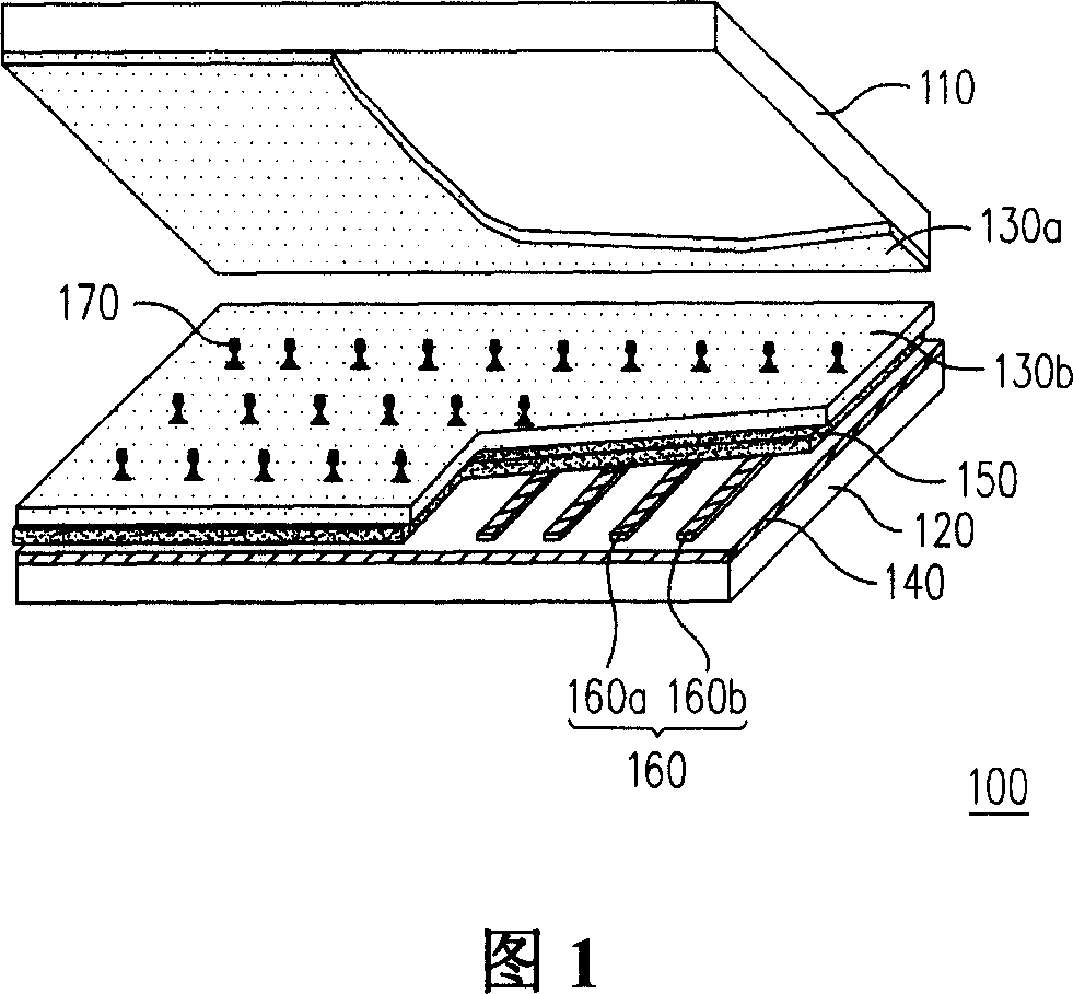
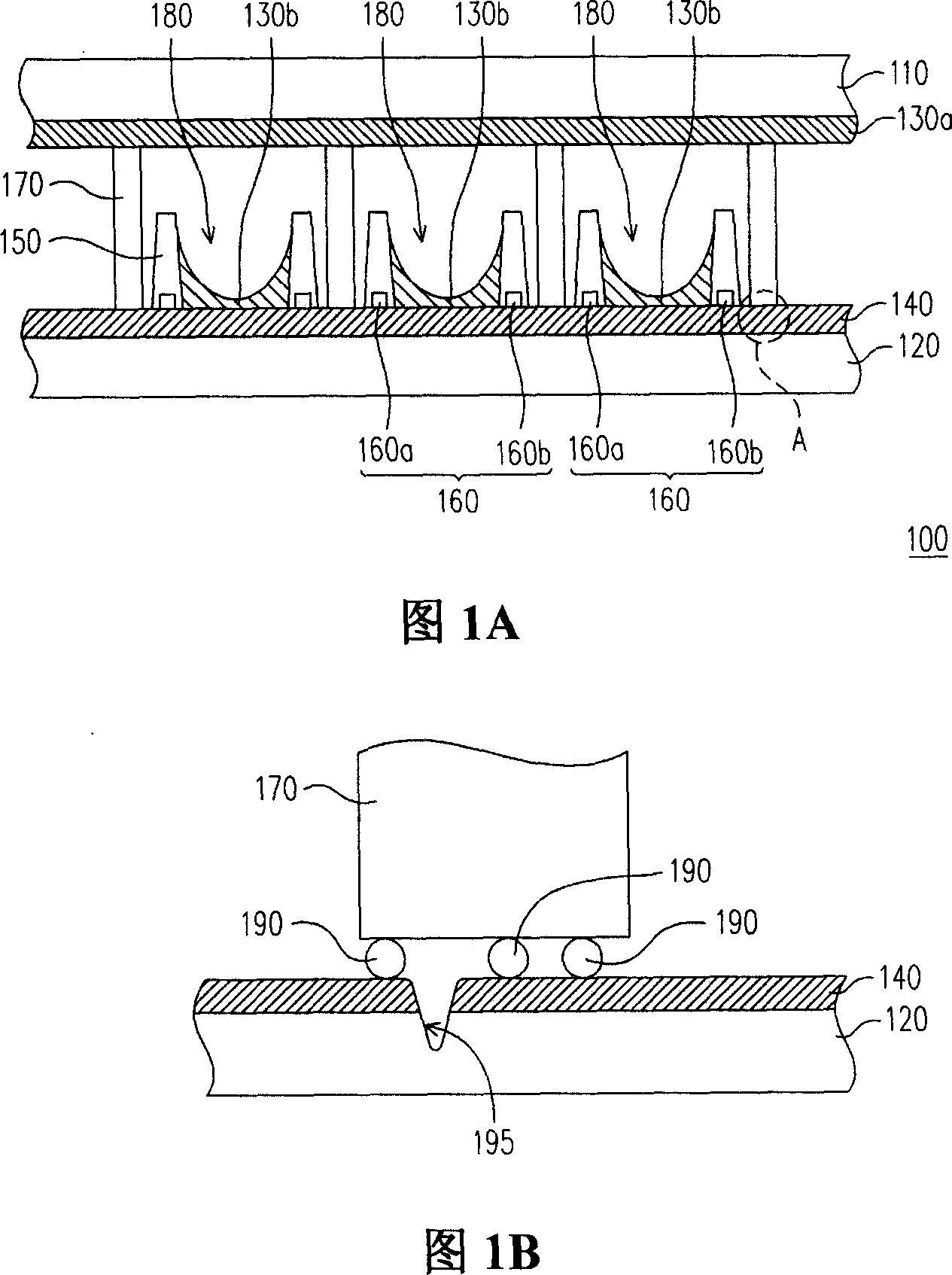
Since the plurality of partition walls 170 are respectively adhered to the lower substrate 120 by glass glue 190, the process of disposing the partition walls 170 will be very time-consuming and cumbersome, which is not conducive to the improvement of the output of the planar light source 100.

Method used


Image

  • Plane light-source and mfg. method
  • Plane light-source and mfg. method
  • Plane light-source and mfg. method

Examples


Embodiment Construction

[0064] Fig. 3 is a schematic diagram of a planar light source in a preferred embodiment of the present invention. Referring to FIG. 3 , the planar light source 300 includes a first substrate 310 , a plurality of electrode groups 320 , a second substrate 330 , a dielectric spacer 340 , a phosphor layer 350 and a discharge gas 360 . The electrode group 320 is disposed on the first substrate 310 . The second substrate 330 is disposed above the first substrate 310 . The dielectric spacer 340 covers the electrode group 320, and the dielectric spacer 340 is connected between the first substrate 310 and the second substrate 330, and the dielectric spacer 340 divides the space between the first substrate 310 and the second substrate 330 It is divided into a plurality of discharge spaces 370 . The phosphor layer 350 is disposed in the discharge space 370 . The discharge gas 360 is disposed in the discharge space 370 .

[0065] Please continue to refer to FIG. 3 , in one embodiment,...


PUM

PropertyMeasurementUnit
Thicknessaaaaaaaaaa

Abstract

A kind of plane lamp source includes the 1st substrates, multiple electrode groups, the 2nd substrates, dielectric partition, the 1st fluorescence layer and discharge gas. The electrode group is set on the 1st substrate. The 2nd substrate is set at the upper of the 1st substrate. The dielectric partition is covered electrode group, whereas the dielectric partition is connected between the 1st substrate and the 2nd substrate, and the dielectric partition divides the space between the 1st substrate and the 2nd substrate into multiple discharge space. The 1st fluorescence layer is set inside the discharge space. The discharge gas is set in the discharge space. The plane lamp source is of simple structure, and suitable to improve the coating square of the fluorescence layer, and avoid the substrate from producing crack.

Description

technical field [0001] The present invention relates to a planar light source and its manufacturing method, and in particular to a planar light source with simple structure and a manufacturing method of the planar light source with simplified process. Background technique [0002] Because the planar light source has good luminous efficiency and uniformity, and can provide a large-area surface light source, the planar light source is widely used in the backlight of the liquid crystal display panel and even other applications. field. The planar light source is a plasma light-emitting device (plasma light-emitting device), which mainly uses electrons to move between the cathode and the anode after they are emitted from the cathode, and the inert gas in the discharge space (discharge space) ( inert gas) to generate collisions to ionize and excite the gas to form plasma. Afterwards, the excited state atoms in the plasma will return to the ground state by emitting ultraviolet ra...

Claims


Application Information

Patent Timeline
IPC IPC(8): H01J61/00H01J61/02H01J61/04H01J61/16H01J9/02G03F7/00
Inventor 张昭仁李素秋曾祥辉谢宇恒吴宏伟
Owner CHUNGHWA PICTURE TUBES LTD
Learn More