Rotating liquid ring pipeline delivery method and equipment for high viscosity fluid
A pipeline transportation and liquid ring technology, which is applied in the pipeline system, gas/liquid distribution and storage, mechanical equipment, etc., can solve the problems of liquid ring damage and instability, and achieve the effect of saving power costs and fuel oil
- Summary
- Abstract
- Description
- Claims
- Application Information
AI Technical Summary
Problems solved by technology
Method used
Image

Examples
Embodiment 1
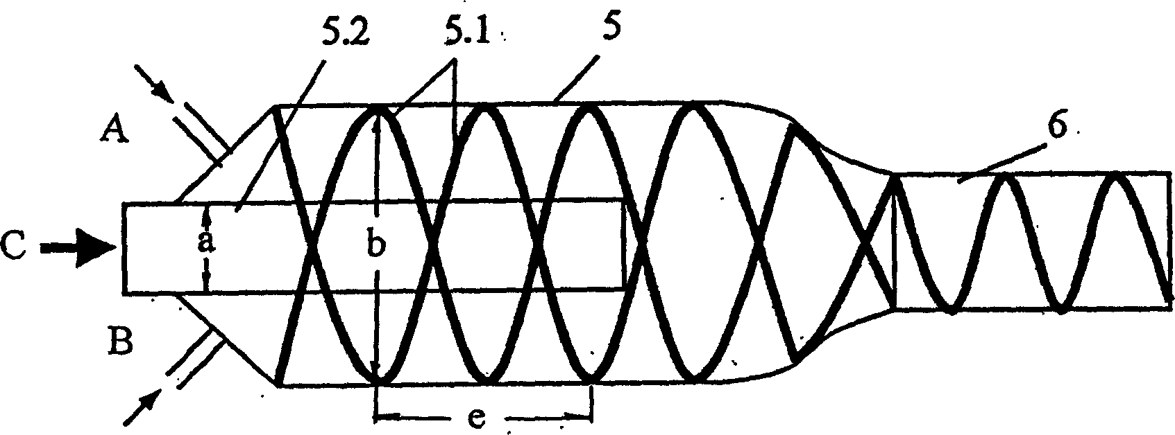
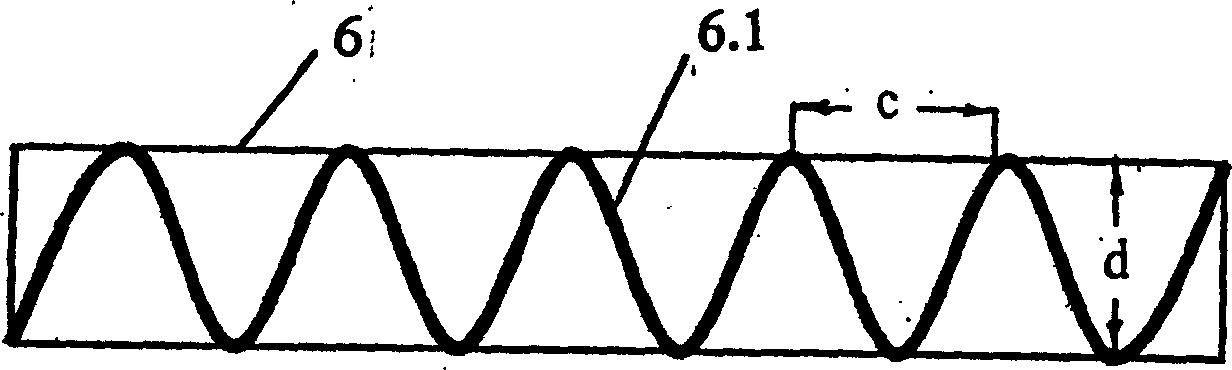
[0025] Water is used as the ring-forming liquid, and high-viscosity crude oil is transported at room temperature. The volume flow ratio of water to crude oil is 3:7. Structural parameters of the outlet pipeline: the ratio of screw pitch to pipe diameter is 1:1; the ratio of spiral plate width to pipe diameter is 0.1:1. Structural parameters of the rotary liquid ring synthesizer: the ratio of the inner diameter of the inner tube through the high-viscosity fluid to the inner diameter of the outlet pipe is 0.75:1; the ratio of the inner diameter of the inner tube through the high-viscosity fluid to the inner diameter of the rotary liquid ring synthesizer is 0.5:1 . In addition to saving fuel without heating the crude oil during transportation, it also reduces the transportation power by more than 81%.
Embodiment 2
[0027] Water is used as the ring-forming liquid, and high-viscosity crude oil is transported at room temperature. The volume flow ratio of water to crude oil is 2:8. Structural parameters of the spiral guide device: the ratio of screw pitch to pipe diameter is 1:1; the ratio of spiral plate width to pipe diameter is 0.07:1. Structural parameters of the rotary liquid ring synthesizer: the ratio of the inner diameter of the inner tube through the high-viscosity fluid to the inner diameter of the outlet pipe is 0.8:1; the ratio of the inner diameter of the inner tube through the high-viscosity fluid to the inner diameter of the rotary liquid ring synthesizer is 0.6:1 . In addition to saving fuel without heating crude oil during transportation, it also reduces transportation power by more than 76%.
PUM
 Abstract
Description
Claims
Application Information
 - R&D
- Intellectual Property
- Life Sciences
- Materials
- Tech Scout
- Unparalleled Data Quality
- Higher Quality Content
- 60% Fewer Hallucinations
Browse by: Latest US Patents, China's latest patents, Technical Efficacy Thesaurus, Application Domain, Technology Topic, Popular Technical Reports.
© 2025 PatSnap. All rights reserved.Legal|Privacy policy|Modern Slavery Act Transparency Statement|Sitemap|About US| Contact US: help@patsnap.com