
Refractive display device

A display device and refractor technology, applied in optics, instruments, optical components, etc., can solve the problem of not being on the driver's seat or a little distance from the steering wheel but still needing to control or obtain the head-up display device, inconvenient application, insufficient convenience, etc. question

Inactive Publication Date: 2005-01-26
吕兴增 +1
View PDF0 Cites 5 Cited by
  • Summary
  • Abstract
  • Description
  • Claims
  • Application Information

AI Technical Summary

Problems solved by technology

However, the fixed-by-wire control method requires the driver to adjust or control within a fixed range during use. The range of use is limited and the convenience is insufficient.
In some specific situations, such as when the driver is not in the driver's seat or a little distance from the steering wheel but still needs to control or obtain information from the head-up display device, it cannot be conveniently applied

Method used


Image

  • Refractive display device
  • Refractive display device
  • Refractive display device

Examples


Embodiment Construction

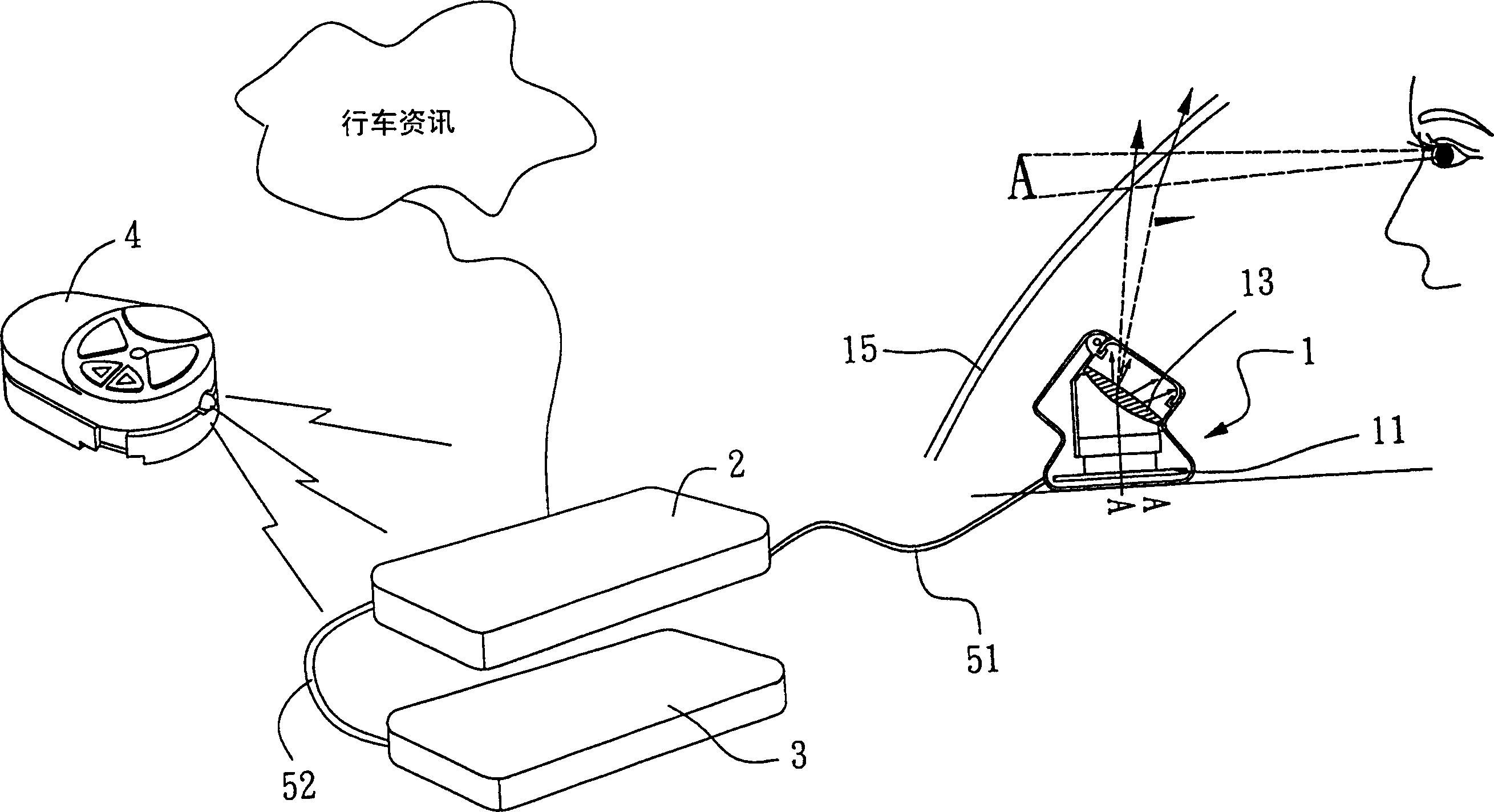
[0015] See figure 1 , which is a schematic diagram of the first embodiment of the present invention. In the figure, the driving information will be transmitted to the function control unit 2, and the function control unit 2 will transmit the information to the image display module 1 through a first signal line 51, and the user will transmit a wireless control signal to the wireless control unit 4 through the wireless control device 4. The signal receiving unit 3 , the wireless signal receiving unit 3 transmits the signal to the function control unit 2 through a second signal line 52 . In this preferred example, there is no limit to the frequency of sending and receiving wireless signals, and it is preferable to use the frequency of infrared wireless sending and receiving as the main one. The function control unit 2 of this preferred example uses buttons to select the information or images to be displayed, and can add other functional options as required, such as on or off. I...


PUM


Abstract

A refracting image display apparatus comprises an image refracting model set which is composed of at least one display unit and light source , a refracting set and a virtual image forming set; a function control unit which is connected through first signal line and sends signals into the image refracting model set; a wireless signal receiving unit which is connected with function control unit through second signal line; a wireless remote control unit which sends wireless signals with one function to the wireless signal receiving device through wireless remote control device; the refracting set is located between the virtual image forming set and display unit to polarizedly refract or reflect light from display unit; the virtual image forming set is used to reflect or refract lights through the refracting set and form the reflecting light into a virtual image; the angle Y between display unit and refracting set is more than zero and less than ninety degrees.

Description

technical field [0001] The invention relates to a refraction display device, in particular to a wireless refraction display device for displaying virtual images. Background technique [0002] Head up display (head up display) is used for the driver of a traffic vehicle (such as a car) to get some important driving information without looking down at the instrument panel during driving, so as to avoid driving during the time when the head is down. An accident occurred because of not looking ahead. Currently, head-up display devices are widely used in vehicles such as automobiles. [0003] However, the existing "projection type" head-up display devices for vehicles are inconvenient to use because they require a large space. The final image formed by the projection method is a real image, and the user often forces the lens of the eye to bend and oppress the eyeball due to close-up observation for a long time; if it is used in a glasses-type display device, the observation tim...

Claims


Application Information

Patent Timeline
IPC IPC(8): G02B27/01G02B27/12H04B5/02
Inventor 吕兴增胡锦标
Owner 吕兴增
Learn More