Control device for working machine

A technology for working machines and control devices, applied in mechanical equipment, transmission control, fluid pressure actuation devices, etc., can solve problems such as pressure loss, system energy efficiency cannot be fully improved, and driving force cannot be obtained immediately, and achieves improved The effect of energy efficiency

Inactive Publication Date: 2005-02-02
KOBELCO CONSTR MASCH CO LTD
View PDF2 Cites 26 Cited by
  • Summary
  • Abstract
  • Description
  • Claims
  • Application Information

AI Technical Summary

Problems solved by technology

[0006] However, the former has a problem in that since a throttle valve is provided downstream of the relief valve, a pressure loss occurs due to the throttle valve, and the energy efficiency of the system cannot be sufficiently improved.
[0007] The problem with the latter is that since there is a time lag from the generation of the overflow flow to the temperature rise of the relief valve, there is a time lag from the moment the overflow flow is generated to the time when the pump flow is cut off and controlled, so that a sufficient reduction in the overflow cannot be obtained. loss effect
In addition, after the overflow flow rate becomes 0, the pump flow rate is still controlled by cut-off due to residual heat detection, and the necessary driving force cannot be obtained immediately

Method used


Image

  • Control device for working machine
  • Control device for working machine
  • Control device for working machine

Examples


Embodiment Construction

[0024] The control device of the working machine in the present invention will be described below based on the embodiments shown in the accompanying drawings.

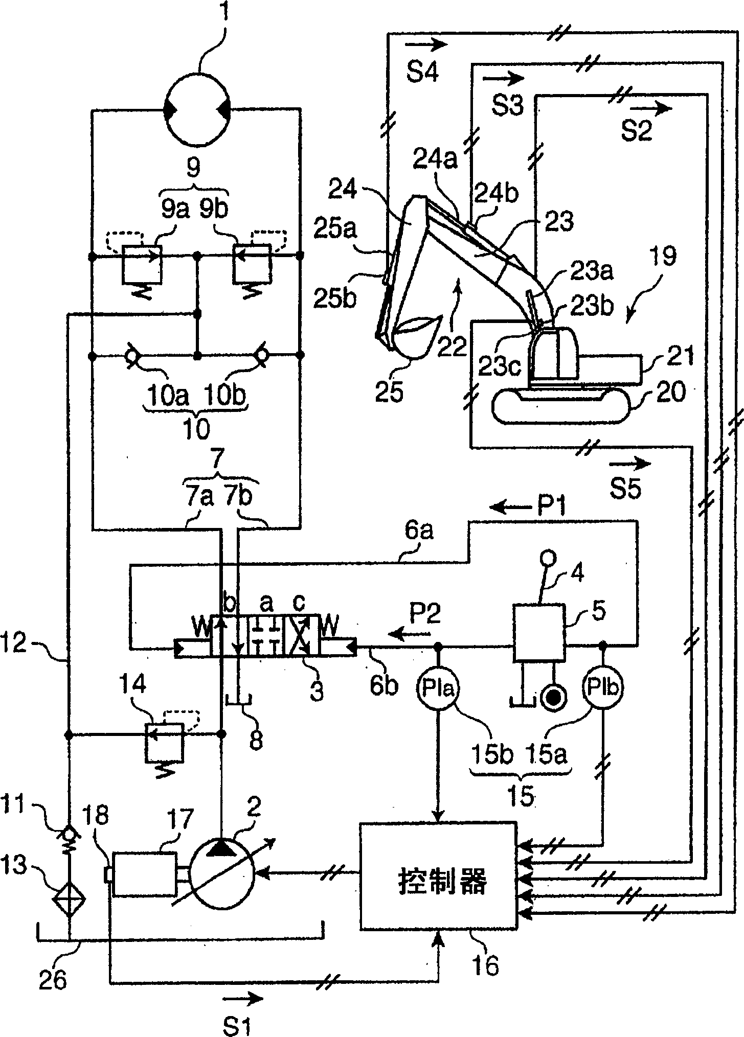
[0025] figure 1 The hydraulic circuit of the hydraulic control device as the control device in the present invention is shown.

[0026] In the figure, 1 is a hydraulic motor as an example of a hydraulic actuator; 2 is a variable capacity hydraulic pump that supplies working oil to the actuator 1.

[0027] 3 is a control valve for controlling the flow rate and direction of hydraulic oil supplied to the actuator 1 . When operating the operating lever 4 as the operating device, the hydraulic control pressure P1 (or P2) derived from the remote control valve 5 acts on the hydraulic control port of any one of the control valve 3 through the control pipeline 6a (or 6b), and the control valve 3 It changes from neutral position a to b or c.

[0028] When the control valve 3 is switched to position b, the pressurized oil from...


PUM


Abstract

A control device for a working machine according to the present invention comprises a capacity variable pump for supplying working oil, a controller for controlling the discharge amount of the pump, a control valve for controlling the working oil discharged from the pump, a hydraulic actuator operated by the working oil from the control valve, an operating lever for operating the hydraulic actuator, and a relief valve to be operated when the pressure of the working oil is a relief pressure or more. The controller has a dynamic emulation model of a hydraulic driving device, and is constituted to estimate the pressure oil flow rate passing through the relief valve from the emulation model according to the operation amount of the operating lever, and to control the pump flow rate of the pump so that the relief flow rate estimation value gets close to zero. According to this, relief loss can be precisely reduced without generating a response delay or pressure loss, and the power can be saved.

Description

technical field [0001] The invention relates to an oil pressure control circuit of an oil pressure working machine. Background technique [0002] In the hydraulic circuit of the working machine, when a large load is applied to the hydraulic cylinder and other actuators, the pressure in the hydraulic circuit will increase. In order to protect the hydraulic device in the circuit, a relief valve is installed. Once the circuit pressure exceeds the relief pressure, the working oil will be released to the oil tank through the relief valve. Therefore, the pressure will not be too large, and damage to the hydraulic device can be prevented. [0003] However, much of the working oil supplied by the pump is directly released to the oil tank through the relief valve without being supplied to the actuator. Therefore, there is a problem that a large amount of pumping power is wasted as a relief valve loss, resulting in a decrease in energy efficiency. [0004] Therefore, cut-off contro...

Claims


Application Information

Patent Timeline
Patent Type & Authority Applications(China)
IPC IPC(8): B66C13/20E02F9/22F15B11/00F15B11/05F15B11/16F15B21/08
CPCF15B2211/30525E02F9/2235F15B11/055E02F9/2225F15B11/165F15B2211/6336F16H61/4061F16H61/4017F15B2211/633F15B2211/6313F15B2211/50518F15B2211/7058F15B2211/30505E02F9/2296F15B2211/5151F15B2211/50527F15B2211/5154F15B2211/31576F15B2211/329F15B2211/3111F16H61/4148F15B2211/20546F15B11/167F15B2211/62F15B21/087
Inventor 今西悦二郎菅野直纪南条孝夫
Owner KOBELCO CONSTR MASCH CO LTD
Why Eureka
Try Eureka