Discharge lamp with phosphor

A technology for luminescent substances and discharge lamps, which is applied in the direction of discharge lamps, components of gas discharge lamps, luminescent materials, etc., and can solve problems such as damage to blue luminescent components, differential quantum efficiency, and loss of luminous intensity

Inactive Publication Date: 2005-02-02
PATENT TREUHAND GESELLSCHAFT FUR ELECTRIC GLUEHLAMPEN MBH
View PDF2 Cites 1 Cited by
  • Summary
  • Abstract
  • Description
  • Claims
  • Application Information

AI Technical Summary

Problems solved by technology

However, there is a problem that, in particular, the commonly used blue luminescent components are damaged by VUV radiation during lamp use and thus lose luminous intensity
Furthermore, the known red-emitting components have rather poor quantum efficiencies when excited with VUV radiation

Method used


Image

  • Discharge lamp with phosphor
  • Discharge lamp with phosphor
  • Discharge lamp with phosphor

Examples


Embodiment Construction

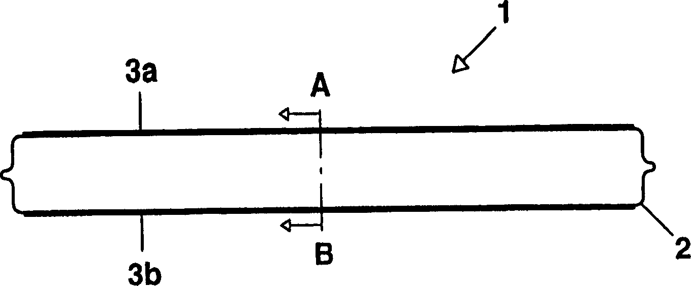
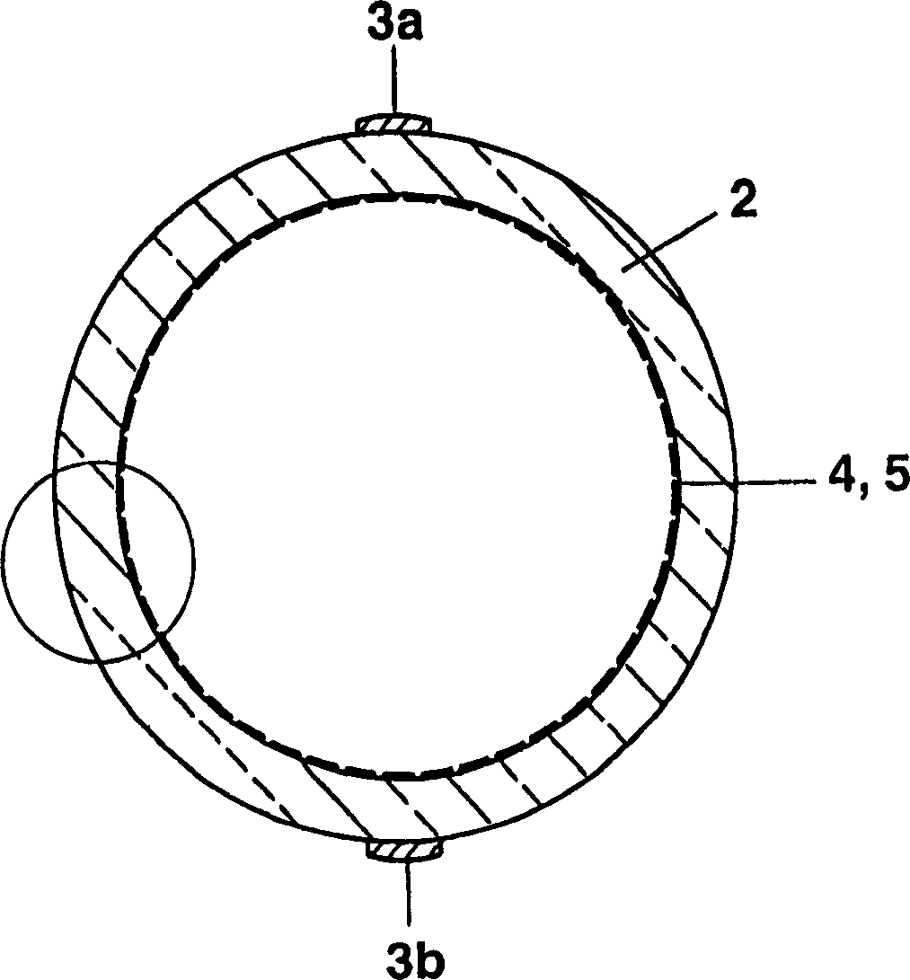
[0071] Refer below Figure 1a~1c A preferred embodiment of the present invention is illustrated.

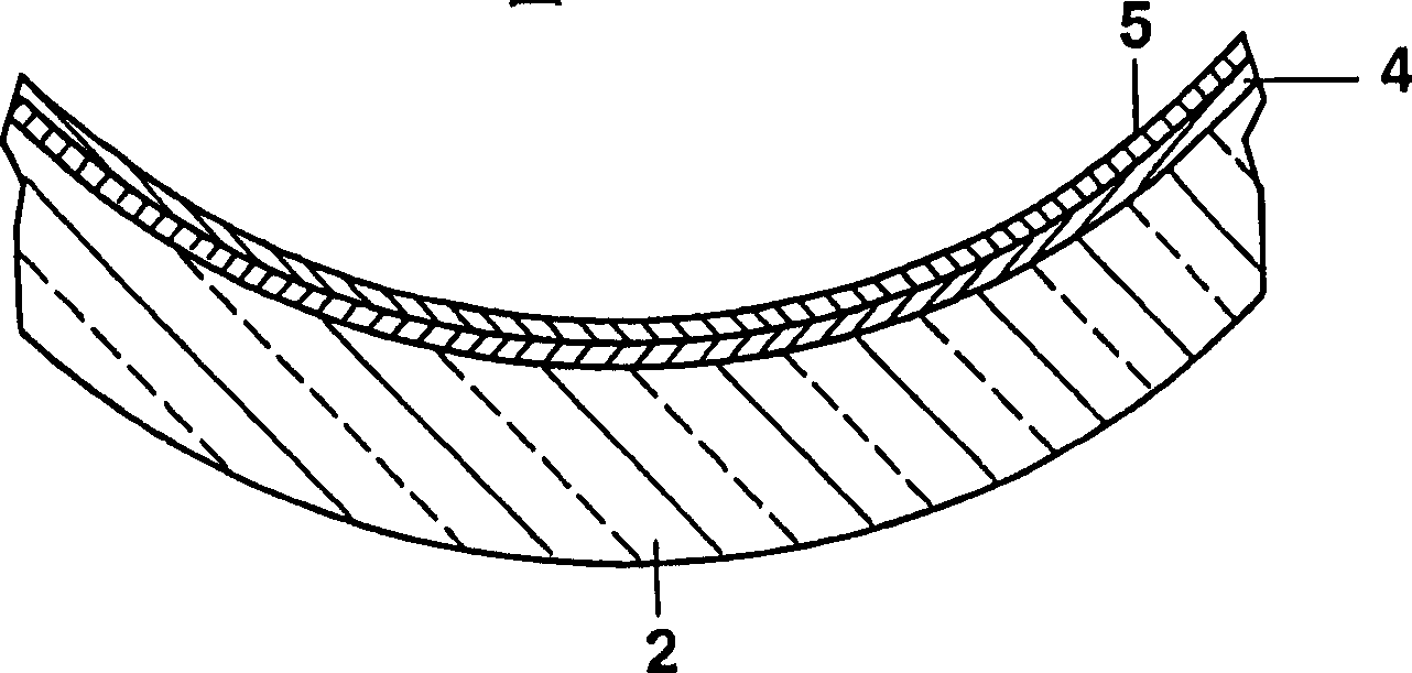
[0072] The discharge lamp 1 has a tubular discharge vessel 2 with an outer diameter of approximately 10 mm, which is sealed at both ends. The discharge vessel 2 is made of soda lime glass and is filled with xenon at a pressure of about 15 kPa as a discharge medium. On the outer side of the wall of the discharge vessel 2 are applied two metal electrodes 3a, 3b formed as linear conductors which lie diametrically opposite and parallel to the longitudinal axis of the discharge vessel. On the inner side of the wall of the discharge vessel 2, an "inner" luminescent substance layer 4 and an "outer" luminescent substance layer 5 are applied. With respect to the "outside" of the discharge medium, the first luminescent substance layer 5 is composed of UVA components Ce 0.99 Ba 0.01 MgAl 11 o 18.99 composition with a layer weight of 1.8 mg / cm 2 . The "outside" second luminescent mat...


PUM


Abstract

A discharge lamp (1) having a discharge vessel (2) which surrounds a discharge medium which emits electromagnetic radiation in the VUV region when the lamp is operating has, on the inner side of the discharge vessel wall, a first phosphor layer, which faces the discharge medium and comprises a UVA component which can be excited by the VUV radiation and is intended to emit electromagnetic radiation in the UVA region. Moreover, the discharge lamp (1) has a second phosphor layer, which can be excited by the UVA radiation and is intended to emit electromagnetic radiation in the visible region. This second phosphor layer either lies beneath the first phosphor layer or is applied to the outer side of the discharge vessel wall. This results in a lower color locus shift compared to a conventional phosphor mixture which can be excited directly by VUV radiation.

Description

technical field [0001] The invention relates to a discharge lamp coated with a luminescent substance which, during operation, emits electromagnetic radiation mainly in the deep ultraviolet region (VUV) into a discharge medium contained within the discharge vessel of the discharge lamp. The so-called far ultraviolet region here refers to the wavelength below about 200 nanometers, especially the range of about 100 nanometers to 200 nanometers. With the aid of the luminescent substance, VUV radiation can be converted into radiation having a longer wavelength, for example in the visible spectral range. [0002] In particular, the invention also relates to discharge lamps of the above-mentioned type which are designed to be operated by means of a dielectric barrier discharge, so-called dielectric barrier discharge lamps. The details of this type of discharge lamp have been described in the prior art and in the applicant's previous patent application, so the basic physical and tech...

Claims


Application Information

Patent Timeline
Patent Type & Authority Applications(China)
IPC IPC(8): H01J65/00C09K11/08C09K11/63C09K11/64C09K11/66C09K11/77C09K11/80C09K11/81H01J1/62H01J61/35H01J61/44H01J61/48H01J63/04H01J65/04
CPCC09K11/666C09K11/7787C09K11/7777C09K11/7774H01J61/44C09K11/7734H01J65/046C09K11/778C09K11/7739C09K11/7792H01J61/48C09K11/7721C09K11/0883C09K11/77347C09K11/77217
Inventor G·胡伯F·耶曼U·米勒M·查肖
Owner PATENT TREUHAND GESELLSCHAFT FUR ELECTRIC GLUEHLAMPEN MBH
Why Eureka
Try Eureka