Control panel structure for microwave oven

A technology for control panel and microwave oven, which is applied in the directions of household stoves/stoves, household heating, lighting and heating equipment, etc., can solve the problem of cumbersome connection work, inability to connect correctly, and inability to correctly set dial buttons 140 and encoders 139 Relative position and other issues

Inactive Publication Date: 2005-02-09
LG ELECTRONICS (TIANJIN) APPLIANCES CO LTD
View PDF0 Cites 0 Cited by
  • Summary
  • Abstract
  • Description
  • Claims
  • Application Information

AI Technical Summary

Problems solved by technology

[0015] In the prior art, in the process of installing the printed circuit board assembly 130 on the rear side of the control dial 110, the connecting screws 152, 153, 154, 154, 154, 155 is connected to the connecting sleeves 112, 113, 114, 115, which is cumbersome and may not be correctly connected to the printed circuit board assembly 130
[0016] As mentioned above, if it cannot be correctly connected to the printed circuit board assembly 130, the relative position of the dial button 140 and the encoder 139 cannot be correctly set.
As a result, one side of the outer peripheral surface of the dial button 140 and one side of the inner peripheral surface of the control panel through hole 111 are in contact with each other, and the dial button 140 cannot be rotated easily.
[0017] This shows that the control panel structure of above-mentioned existing microwave oven still has many defectives, and Cheng waits to be improved

Method used


Image

  • Control panel structure for microwave oven
  • Control panel structure for microwave oven
  • Control panel structure for microwave oven

Examples


Embodiment Construction

[0046] Below in conjunction with the accompanying drawings and preferred embodiments, the specific implementation, structure, features and effects of the present invention will be described in detail as follows.

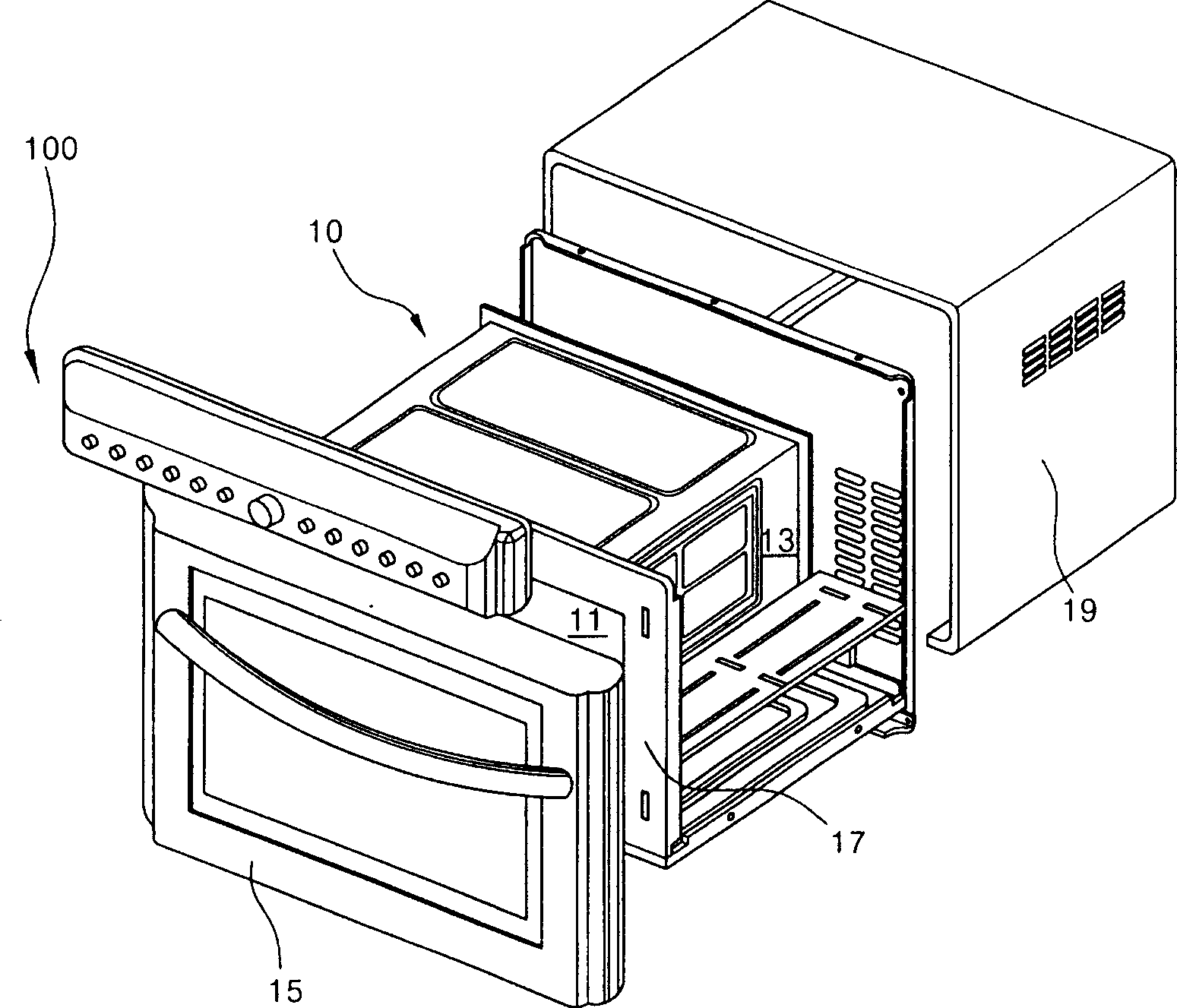
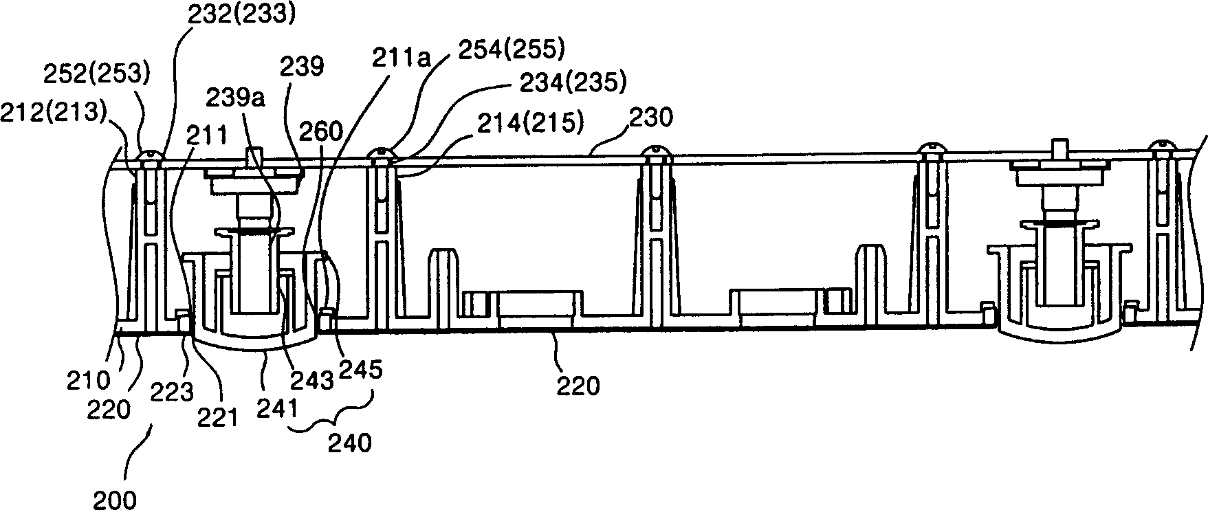
[0047] see image 3 , Figure 4 As shown, the control panel structure of the microwave oven of the present invention, the function of the control panel 200 arranged on the front side of the microwave oven is to input various operation signals for controlling the operation of the microwave oven, and to display various conditions of the operation of the microwave oven externally.

[0048] On the control dial 210 of the front appearance of the above-mentioned control panel 200 are formed several control panel perforations 211 penetrating through the dial button 240 to be described below. The inner peripheral surface of the control panel through hole 211 has a step portion 211a protruding backward. And a control cover 220 is installed on the front of the control dial 2...


PUM


Abstract

The control panel structure for microwave oven includes control dial plate, controller hood, printed circuit board assembly, scale disc knob and guide ring. It has several connecting casings in the inner side of the control panel, control hood in front of the control dial plate, printed circuit board assembly with coder in the front of the control dial plate, outward extending scale disc knob combined to the coder, and guide ring for guiding the scale disc knob. When the printed circuit board assembly is mounted to the back side of the control panel, the relative position between the scale disc knob and the coder may be set correctly.

Description

technical field [0001] The present invention relates to a control panel of a microwave oven, more specifically to an invention on the structure of a control panel of a microwave oven capable of correctly setting the relative positions of buttons and encoders. Background technique [0002] figure 1 It is a three-dimensional schematic diagram of a conventional microwave oven structure. As shown in the figure, the inside of the cavity assembly 10 of the microwave oven forms a cooking chamber 11 that utilizes microwaves or heat sources to heat food; one side of the cavity assembly 10 has an electric control room 13, and a magnetron ( MAGNETRON), high voltage transformers (TRANSFORMER) and other electronic components. [0003] A cooking chamber door 15 is provided on one side of the front panel 17 at the front of the cavity assembly 10 . The cooking chamber door 15 can be turned to open and close the above-mentioned cooking chamber 11 towards the front side of the microwave ov...

Claims


Application Information

Patent Timeline
IPC IPC(8): F24C7/02F24C7/08
Inventor 黄根在
Owner LG ELECTRONICS (TIANJIN) APPLIANCES CO LTD
Why Eureka
Try Eureka