Method of manufacturing sensor and sensor

A manufacturing method, sensor technology, used in instruments, scientific instruments, measuring devices, etc.

Inactive Publication Date: 2005-02-09
NGK SPARK PLUG CO LTD
View PDF3 Cites 11 Cited by
  • Summary
  • Abstract
  • Description
  • Claims
  • Application Information

AI Technical Summary

Problems solved by technology

Glass welding requires high temperature heat treatment

Method used


Image

  • Method of manufacturing sensor and sensor
  • Method of manufacturing sensor and sensor
  • Method of manufacturing sensor and sensor

Examples


Embodiment Construction

[0083] Embodiments to which the present invention is applied will be described in detail below with reference to the accompanying drawings.

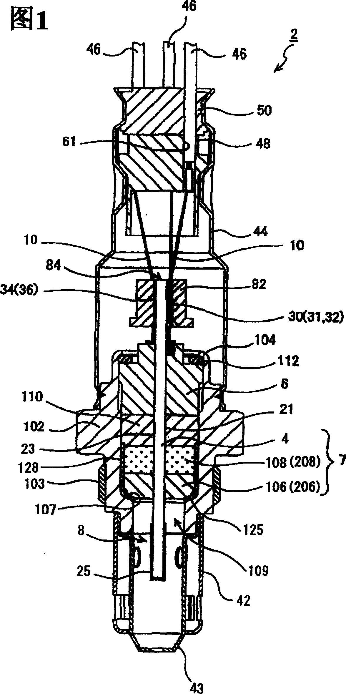
[0084] This embodiment is a full-range air-fuel ratio sensor 2 (hereinafter may be referred to as an air-fuel ratio sensor 2 ) as a gas sensor. In order to be used in the air-fuel ratio feedback control in various internal combustion engines including automotive internal combustion engines, the air-fuel ratio sensor 2 includes a detection element (gas sensor element) for detecting a specific gas or a measured object, which is contained in the exhaust gas and installed in the exhaust pipe of the internal combustion engine.

[0085] FIG. 1 is a cross-sectional view showing the overall configuration of an air-fuel ratio sensor 2 implemented by applying the method of the present invention.

[0086] The air-fuel ratio sensor 2 includes: a tubular metal casing 102 with a male threaded portion 103 formed on the outer surface, which is suitable...


PUM


Abstract

In a method of manufacturing a sensor, firstly, a plate-type detection element is inserted through an element-insertion through-hole of a first powder-compacted ring. Secondly, a flange section including at least the first powder-compacted ring is integrally assembled to the plate-type detection element, applying axially compressive pressure to the first powder-compacted ring so as to compressively deform the first powder-compacted ring such that the cross-sectional area of the element-insertion through-hole is reduced. Thirdly, the flange section is engaged, directly or via an intermediate member, with the stepped portion of the metallic shell at the time of disposing of the plate-type detection element in the through-hole of the metallic shell.

Description

technical field [0001] The present invention relates to a manufacturing method of a sensor and a sensor. Background technique [0002] Conventionally known sensors include oxygen sensors configured to hold a detection element having a tubular shape (hereinafter may be referred to as a tubular detection element) within a metal case. Some oxygen sensors use a tubular detection element having a flange portion integrally formed at a substantially central position in the axial direction such that the flange portion faces rearward and protrudes radially outward. The tubular detection element is disposed inside the metal case such that the flange portion engages with the stepped portion projecting radially inward from the wall surface of the through hole of the metal case directly or through another member such as a packing. [0003] Meanwhile, a recently proposed oxygen sensor uses a detection element having a plate shape (a detection element having a laminated structure; hereina...

Claims


Application Information

Patent Timeline
Patent Type & Authority Applications(China)
IPC IPC(8): G01N27/407
CPCY10T29/49929G01N27/4077
Inventor 松尾康司石川聪
Owner NGK SPARK PLUG CO LTD
Why Eureka
Try Eureka