Turnover spring for button switch and button switch using the same

A switch and button technology, applied in the field of button switch structure, can solve the problems of cost increase, mold manufacturing and forming complexity, etc.

Inactive Publication Date: 2005-02-09
ALPS ALPINE CO LTD
View PDF1 Cites 2 Cited by
  • Summary
  • Abstract
  • Description
  • Claims
  • Application Information

AI Technical Summary

Problems solved by technology

However, since the rubber material is molded and manufactured using a mold, if the shape of the skirt is complicated, the manufacturing and molding of the mold become complicated and the cost increases.

Method used


Image

  • Turnover spring for button switch and button switch using the same
  • Turnover spring for button switch and button switch using the same
  • Turnover spring for button switch and button switch using the same

Examples


Embodiment Construction

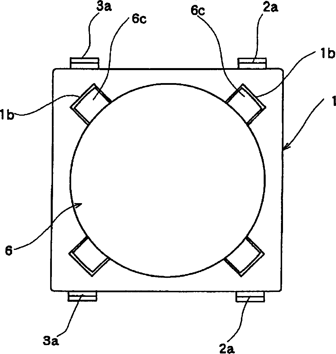
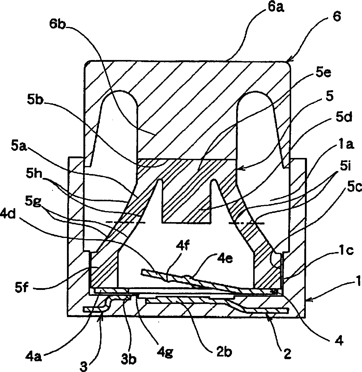
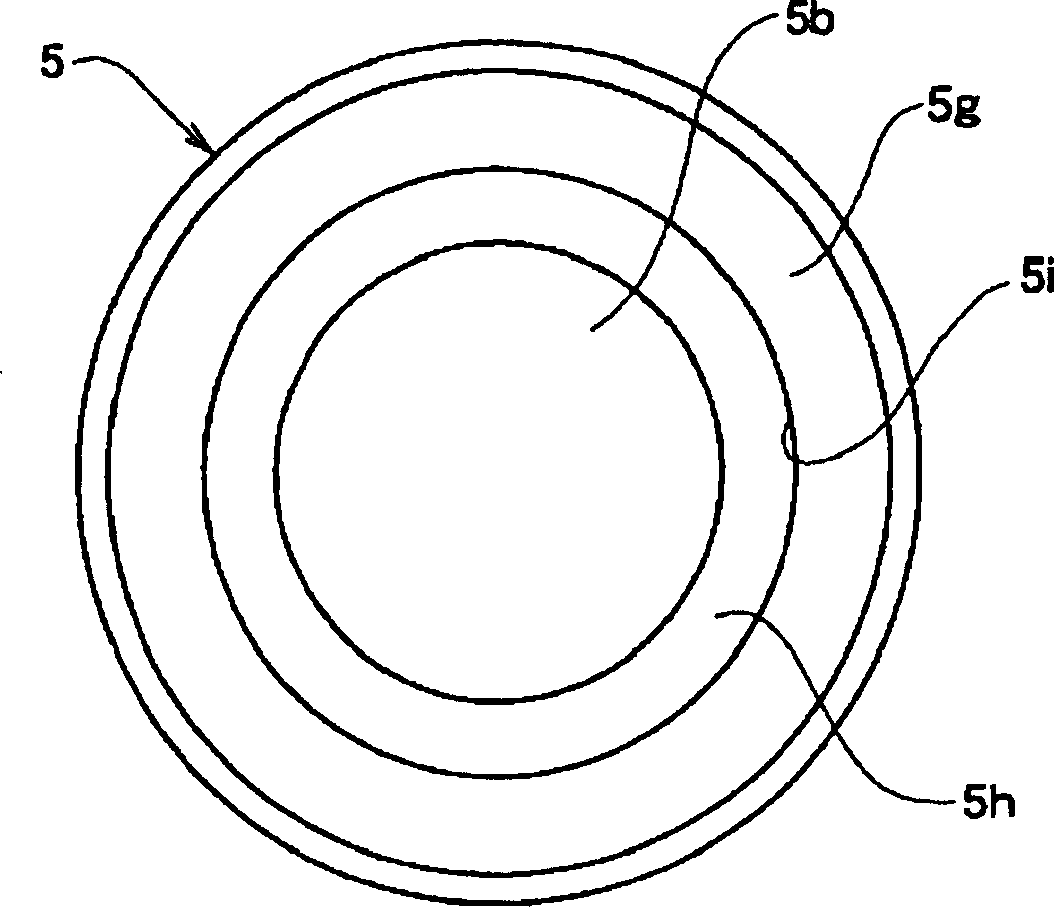
[0026] Use the following Figure 1 to Figure 5 , an embodiment of the flip spring for the push button switch and the push button switch of the present invention will be described. figure 1 is the top view of the push button switch, figure 2 is a cross-sectional view of a push button switch, image 3 is the top view of the flip spring, Figure 4 is the cross-sectional view of the flip spring, Figure 5 It is an explanatory diagram showing the force characteristic of the reversing spring.

[0027] The case 1 is made of an insulating material such as synthetic resin, and is formed in a rectangular box shape with an open top. In the opening of the housing 1, a receiving portion 1a is formed; the inner bottom of the receiving portion 1a is molded on the above-mentioned pair of fixed contacts 2, 3 formed of conductive metal materials such as brass by insert molding or other methods. on the shell 1, and make it form a whole with the shell 1.

[0028] In addition, guide groove...


PUM


Abstract

The present invention provides a reversing spring for a push-button switch and a push-button switch using the same, easy to manufacture and capable of obtaining a desired click feeling by a simple structure. The spring comprises a base part 5f; a pressing part 5e of which the upper end is provided with a pressing face part 5b; and a skirt part 5a bendably formed between the base part 5f and the pressing part 5e and obtaining the click feeling by buckling with pressure of the pressing part 5e. The skirt part 5a is formed by an inclined plane which is tapered as it is headed from the base part 5f to the pressing part 5e, and the inclined plane is formed by a first and a second inclined planes 5g, 5h different in angle of inclination between the sides of the base part 5f and the pressing part 5e. Then, a click adjusting part 5i adjusting the click feeling when the skirt part 5a is buckled at an intersection part of the first and the second inclined planes 5g, 5h.

Description

technical field [0001] The present invention relates to the structure of a push button switch used as an operation switch of various electronic devices, and particularly relates to the structure of a push button switch using a rubber spring as a flip spring. Background technique [0002] The structure of the push button switch in the past is known (for example, refer to Patent Document 1): in the housing portion of the housing on which the fixed contact is installed, a movable contact opposite to the fixed contact is arranged, and the movable contact is pressed to the fixed contact. The rubber spring on the contact side returns the operating shaft by the ejection force of the rubber spring. [0003] Hereinafter, the conventional push button switch structure will be described in detail with reference to the drawings. [0004] Image 6 It is a top view of a conventional push button switch, Figure 7 It is a sectional view of a conventional push button switch. [0005] In th...

Claims


Application Information

Patent Timeline
Patent Type & Authority Applications(China)
IPC IPC(8): H01H13/48H01H5/30H01H13/26H01H13/52
CPCH01H13/14H01H13/26H01H2205/004H01H2235/008
Inventor 河原博幸
Owner ALPS ALPINE CO LTD
Why Eureka
Try Eureka