Surface mounting type antenna, antenna apparatus and radio communication apparatus

A surface-mounted, antenna technology, applied in antennas, resonant antennas, electrical short antennas, etc., can solve the problems of difficulty in reducing the size of the surface-mounted antenna 61, unable to obtain stable antenna characteristics, and difficult to reduce the size of the antenna, and achieve impedance change. effect of large, increased bandwidth, increased gain

Inactive Publication Date: 2005-02-09
KYOCERA CORP
View PDF2 Cites 2 Cited by
  • Summary
  • Abstract
  • Description
  • Claims
  • Application Information

AI Technical Summary

Problems solved by technology

[0008] But when Figure 4 In the conventional surface mount type antenna 61 shown, the problem is that in order to match the operating frequency of the surface mount type antenna 61 to the lower frequency f1 and the upper frequency f2 of the radio signal used in the communication system, it is necessary to adjust the helix The length and spacing of the radiation electrodes 62 and 63 are adjusted, and this adjustment requires a lot of man-hours
[0009] In addition, there is also a problem that, when trying to increase the dielectric constant of the substrate 66 to reduce the size of the surface-mounted antenna 61, an unnecessary gap is accidentally generated between the spirally long radiation electrodes 62 and 63 and the ground conductor layer 73. resonance mode, and stable antenna characteristics applicable to dual frequencies cannot be obtained, and it is difficult to reduce the size of the surface mount type antenna 61
[0010] Furthermore, in the antenna of the mobile communication terminal disclosed in JP-A 2002-204120, there is a problem in that it is difficult to apply surface mount
[0011] Furthermore, in the antenna device disclosed in JP-A 2002-314330, there is a problem in that since the radiation electrode has a planar pattern, the size of the antenna is increased and it is difficult to reduce the size of the antenna

Method used


Image

  • Surface mounting type antenna, antenna apparatus and radio communication apparatus
  • Surface mounting type antenna, antenna apparatus and radio communication apparatus
  • Surface mounting type antenna, antenna apparatus and radio communication apparatus

Examples


Embodiment Construction

[0067] Hereinafter, preferred embodiments of the present invention will be described with reference to the accompanying drawings.

[0068] Hereinafter, embodiments of the surface mount type antenna, antenna device, and radio communication device of the present invention will be explained with reference to the accompanying drawings.

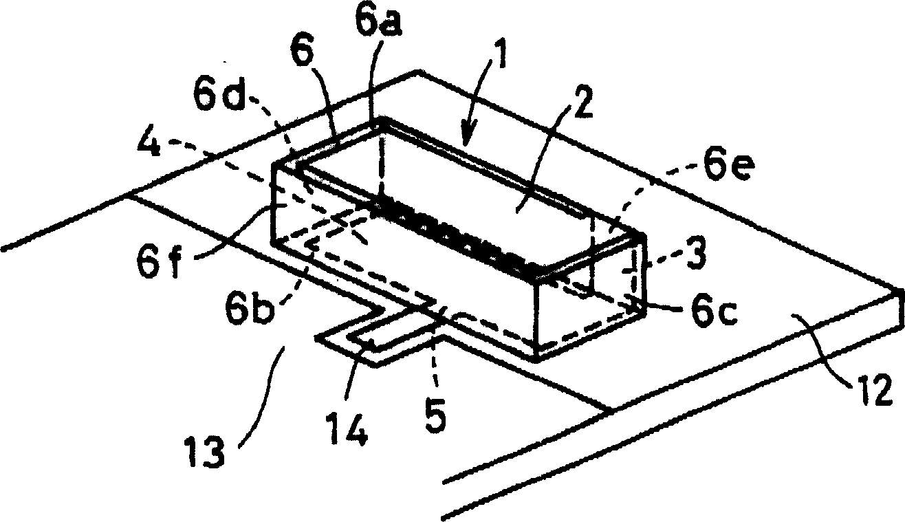
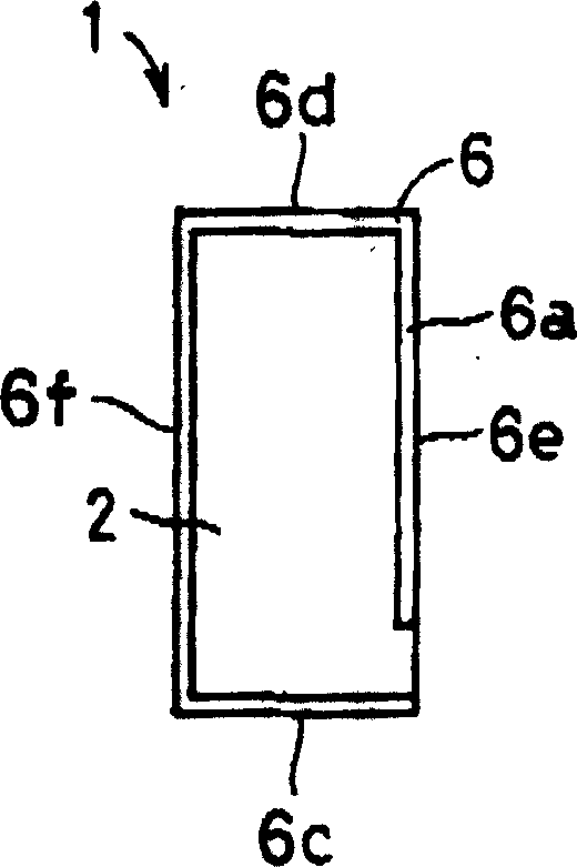
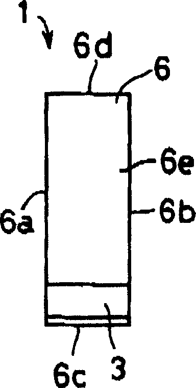
[0069] Figure 1A is a perspective view showing a surface mount type antenna according to a first embodiment of the present invention and an antenna device according to the first embodiment of the present invention using this surface mount type antenna. Figure 1B yes Figure 1A Plan view of the surface mount antenna shown. Figure 1C yes Figure 1A Right side view of the surface mount antenna shown. Figure 1D yes Figure 1A Bottom view of the surface mount antenna shown.

[0070] The surface mount type antenna 1 according to the first embodiment of the present invention includes a substrate 6 , a first radiation electrode 2 , a second radi...


PUM


Abstract

The surface mounting type antenna includes a rectangular parallelepiped base body, a group of radiation electrodes and a feeder terminal. The group of radiation electrodes includes radiation electrodes formed on a first pair of side faces so as to extend from one end face side to another end face side thereof, and a radiation electrode formed on the one end face side of one side face of a second pair of side faces, the radiation electrode being connected to the radiation electrodes formed on the first pair of side faces. The feeder terminal is formed on a part of another side face of the first pair of side faces, the part being in a vicinity of another side face of the second pair of side faces, the feeder terminal being connected to the group of radiation electrodes.

Description

technical field [0001] The present invention relates to a surface mount type antenna as a dual-frequency small antenna applicable to mobile communication devices such as portable phones, and an antenna device, and a surface mount type antenna and an antenna device using the same radio communication equipment. Background technique [0002] The reduction in size of mobile communication devices such as portable phones has been rapidly advanced. Considering an antenna as a component of a mobile communication device, efforts are being made to address reduction in size by using a surface mount type antenna or the like. will refer to Figure 4 A perspective view of , explaining a conventional surface mount type antenna and an example of an antenna device using such a surface mount type antenna. [0003] exist Figure 4 In , reference numeral 61 denotes a surface mount type antenna, which is mounted on a mounting substrate 72 to constitute an antenna device. exist Figure 4 In th...

Claims


Application Information

Patent Timeline
Patent Type & Authority Applications(China)
IPC IPC(8): H01Q13/08H01Q1/24H01Q1/38H01Q5/10H01Q9/04
CPCH01Q9/0442H01Q9/0407H01Q1/243H01Q1/38
Inventor 佐藤昭典生田贵纪
Owner KYOCERA CORP
Why Eureka
Try Eureka