Channel-cranium electro-stimulating device and method

An electric stimulation, transcranial technology, applied in artificial respiration, physical therapy, etc.

Inactive Publication Date: 2005-02-16
KALACO SCI
View PDF2 Cites 7 Cited by
  • Summary
  • Abstract
  • Description
  • Claims
  • Application Information

AI Technical Summary

Problems solved by technology

[0006] An additional potentially harmful disa

Method used


Image

  • Channel-cranium electro-stimulating device and method
  • Channel-cranium electro-stimulating device and method
  • Channel-cranium electro-stimulating device and method

Examples


Embodiment Construction

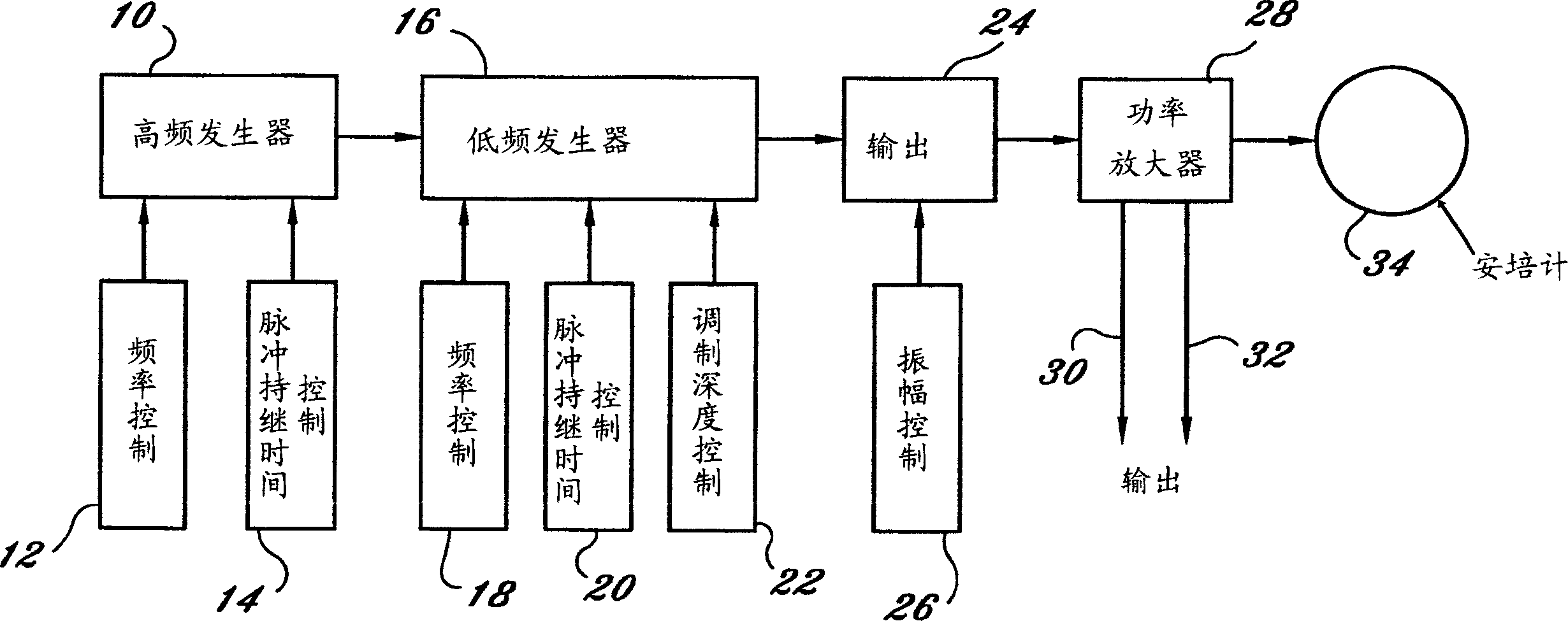
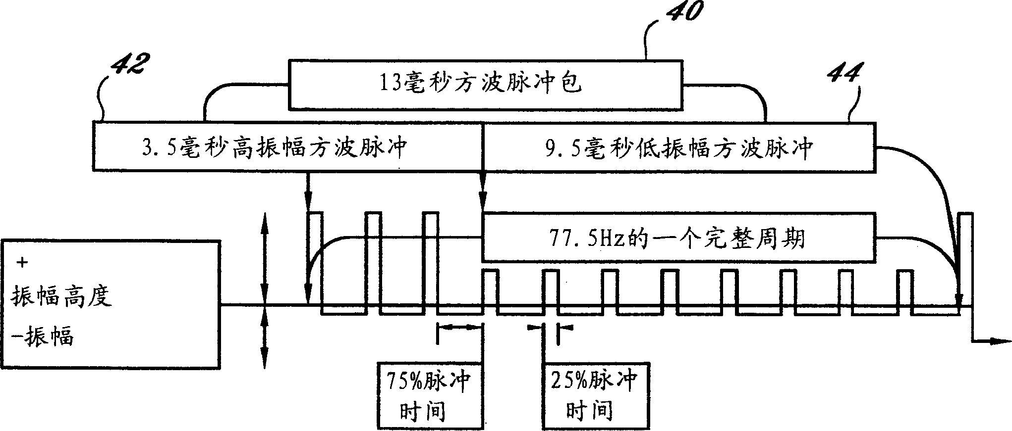
[0020] A preferred embodiment of the present invention and its operation will now be described with reference to the accompanying drawings. figure 1 is a schematic diagram of the salient operational features of a circuit capable of producing a unique asymmetrical triple waveform implementation useful for a variety of transcranial electrical stimulation applications. connect figure 2 The unique waveforms described in detail can cause little to no discomfort to the instrument user.

[0021] as figure 1 As described, the fundamental high frequency current signal is generated by a high frequency generator 10, which may use a frequency control 12 and a pulse duration control 14 to establish the fundamental frequency and provide the difference between the positive and negative portions of each pulse generated by the generator 10. The asymmetry required between. Typically, generator 10 may include a crystal oscillator operating between 1000 and 1200 kilohertz, which frequency is ...


PUM


Abstract

The invention discloses an electric stimulator through skull and its method, including the first generator which generates bipolar impulses of the first preset frequency, the modulation control signal source which generates the second output frequency lower than the first preset frequency and enables the output impulses of the first impulse generator to change amplitudes over the preset asymmetry graphs of the modulation control signals' frequency, and the designed output polar in order to make the signals' asymmetry graph apply to the attached patient' scalp.

Description

Background technique [0001] Bioelectrical stimulation devices have been developed to apply electrical current pulses to a patient through electrodes located on opposite sides of the patient's brain. Pulses of electrical current at a selected frequency are used to interact with the patient's central nervous system. Commonly referred to as transcranial electrical stimulators (TCES) or cranial electrical stimulators (CES), such devices have been used in a number of non-invasive procedures, such as producing pain relief, reducing or controlling migraines, and for Some other treatments and electric anesthesia. [0002] The earliest prototype of the transcranial electrical stimulation device originated in Russia. These initial designs, while successfully used in several different treatment modalities, had serious disadvantages of discomfort to the wearer or patient. In individual cases these earlier cranial stimulation devices even caused pain to the patient. The cause of the di...

Claims


Application Information

Patent Timeline
IPC IPC(8): A61N1/36
Inventor Y·S·卡特斯内尔森
Owner KALACO SCI
Why Eureka
Try Eureka