Pump system for conveying lubricating oil

A pump system and lubricating oil technology, applied in the field of pump system, can solve the problems of cooling and conveying oil volume, excessive wear of cutting chain, unsatisfactory cutting effect, etc., and achieve the effect of reducing mechanical loss and cost

Inactive Publication Date: 2005-02-16
ANDREAS STIHL AG & CO KG
View PDF0 Cites 15 Cited by
  • Summary
  • Abstract
  • Description
  • Claims
  • Application Information

AI Technical Summary

Problems solved by technology

Searching for an at least near-optimal oil delivery at operating temperature can lead to an initial oil delivery that is too small after long interruptions in service when the oil cools down
This can cause excessive wear on the cutting chain
The cutting effect is unsatisfactory when the amount of oil delivered is too small

Method used


Image

  • Pump system for conveying lubricating oil
  • Pump system for conveying lubricating oil
  • Pump system for conveying lubricating oil

Examples


Embodiment Construction

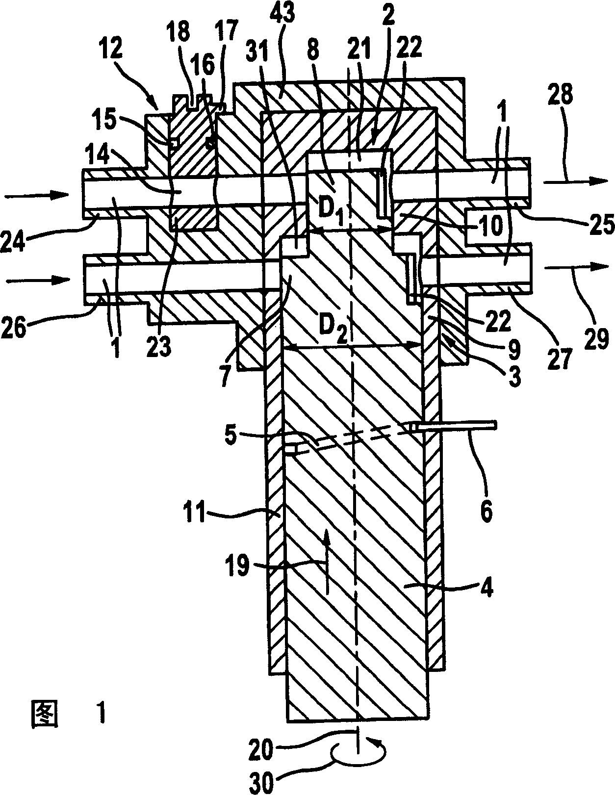
[0026] FIG. 1 shows a sectional view of a pump system for delivering lubricating oil 1 to a cutting chain (not shown) of a chain saw. The pump system includes a user-adjustable oil pump 2 and a base oil pump 3 . The two oil pumps 2, 3 have input pipes 24, 26 and output pipes 25, 27 respectively. The lubricating oil 1 is sucked in through the inlet pipes 24 , 26 and pushed out through the outlet pipes 25 , 27 . The adjustable oil pump 2 and the base oil pump 3 communicate with the same oil tank (not shown) through respective inlet pipes 24 , 26 . The two output pipes 25, 27 lead to the cutting chain of the chain saw, so the two oil pumps 2, 3 are connected in parallel. In order to realize multiple conversion stages, other adjustable oil pumps 2 can be connected in parallel.

[0027] The pump system may be a system with a gear pump, a diaphragm pump or the like, but in the illustrated embodiment is implemented as a piston pump system. For this purpose, a piston part 4 has a ...


PUM


Abstract

A pump system for conveying lubricating oil to a cutting chain of a chain saw is provided. The pump system comprises at least one first oil pump, wherein a quantity of oil being conveyed thereby is adjustable by an operator of the chain saw.

Description

technical field [0001] The invention relates to a pump system for supplying lubricating oil to a cutting chain of a chain saw with the features of the preamble of claim 1 . Background technique [0002] The chain saw has a guide rail, on whose annular edge a cutting chain with individual chain links is guided. The joints of the chain links and the cutting teeth are subjected to heavy loads during operation. In order to avoid excessive wear and improve the cutting results, lubricating oil is supplied to the cutting chain by means of a pump system. [0003] According to the processed cuttings, determine the amount of oil delivery. When the types of wood to be cut are different, the amount of lubricating oil required to achieve a good cutting effect is different. For this purpose, known pump systems have user-adjustable oil pumps, the operator of the chain saw adjusting the delivery rate of lubricating oil depending on the cut to be processed. [0004] It turns out that the...

Claims


Application Information

Patent Timeline
Patent Type & Authority Applications(China)
IPC IPC(8): F04B3/00F04B7/06F04B23/06F04B49/12F04B53/18F16N13/04
CPCF04B53/18F04B7/06F04B3/00F16N13/04F04B49/12F04B23/06
Inventor B·迪尔
Owner ANDREAS STIHL AG & CO KG
Why Eureka
Try Eureka