Method for designing low-rate revolution centrifugal pump impeller

A technology of centrifugal pump impeller and design method, which is applied in the directions of pumps, pump components, mechanical equipment, etc., can solve the problems of small flow channel clearance, low efficiency of design conditions, and increased difficulty in casting process, so as to achieve the effect of efficient and reliable use

A technology of centrifugal pump impeller and design method, which is applied in the directions of pumps, pump components, mechanical equipment, etc., can solve the problems of small flow channel clearance, low efficiency of design conditions, and increased difficulty in casting process, so as to achieve the effect of efficient and reliable use

CN1580577AInactive Publication Date: 2005-02-16JINING ANTAI MINING EQUIP MFG CO LTD

Image

  • Method for designing low-rate revolution centrifugal pump impeller
  • Method for designing low-rate revolution centrifugal pump impeller

Examples


Embodiment Construction

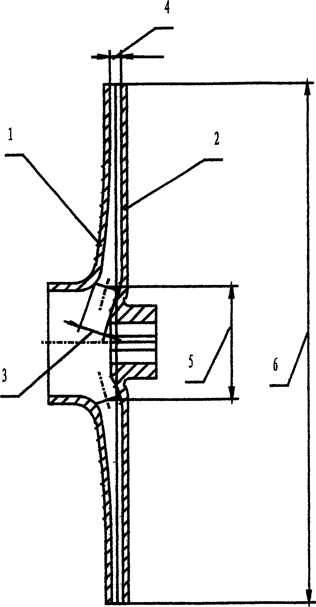
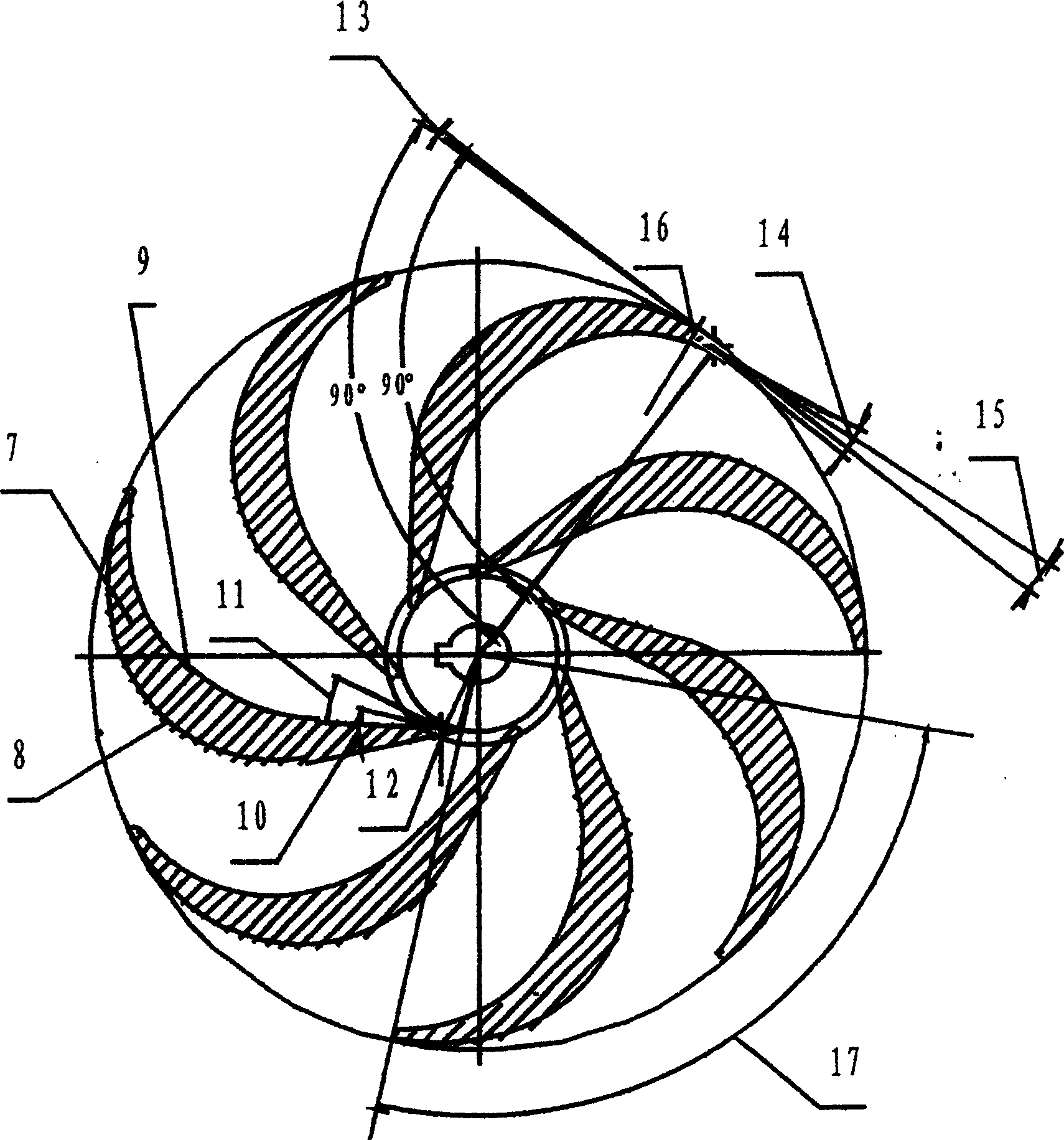
[0038] figure 1 and figure 2 Together determine the impeller shape for this embodiment. Like most centrifugal pump impellers, it has an impeller front cover (1) and an impeller rear cover (2), and is a closed impeller. If there is no impeller front cover plate and the impeller rear cover plate is very small, promptly make semi-open type or open impeller, also do not affect the enforcement of the present invention, because what the present invention controls is the parameter of blade (7). In the figure, the convex surface of the blade is also called the blade working surface (8), and the concave surface of the blade is also called the blade back (9). 2 ′(13) is designed to be 0 degrees, which can be obtained from β 2 'The angle between the two corner sides and the third side is 90 degrees. It can be seen that the outlet placement angle β on the back of the blade 2"(14) is designed as 2β 2 degrees, so the outlet placement angle β of the impeller blade 2 =(β 2 '+β 2 ") / 2...


PUM


Abstract

This invention relates to a vane wheel designing method for a low ratio revolution certrifugal pump used in the behavior of low ratio revolution of high ratio revolution namely high delivery lift small flow characterizing in namely low delivery lift big flow linking the geometric parameters of the vane and the designed behavior point performance by several new relation formulas to reach the designing result of coincidence of the used situation of the design and the behavior of the maximum efficiency point and the power maximum point.

Description

Technical field [0001] The invention relates to a design method for the main parts of a non-variable pump, especially for use in the low specific speed working condition, that is, the high lift and small flow condition, and also in the high specific revolution working condition, that is, the low head and large flow The impeller design method of low specific speed centrifugal pump used in working conditions. Background technique [0002] At present, the known impeller design methods of low specific speed centrifugal pumps all reduce the diameter of the impeller as much as possible to improve the efficiency of the pump while meeting the head requirements of the design working conditions of the pump. It can ensure the efficient and reliable use of the centrifugal pump under the condition of low specific speed, that is, high head and small flow. If it is used under the condition of high specific speed, that is, low head and large flow, the power will be overloaded and the motor ...

Claims


Application Information

Patent Timeline
16 Feb 2005
Publication
CN1580577A
IPC
F04D29/24
Inventors
陆伟刚