Protection and guidance apparatus for cable and the like

A guiding device and similar technology are applied in the installation of cables, cable arrangement between relative moving parts, cable laying equipment, etc., which can solve the problems of increased collision speed, easy wear, accelerated shaft damage, etc., and achieve stability and Effects of smooth operation, impact noise suppression, and stress concentration avoidance

Active Publication Date: 2005-02-16
TSUBAKIMOTO CHAIN CO
View PDF1 Cites 18 Cited by
  • Summary
  • Abstract
  • Description
  • Claims
  • Application Information

AI Technical Summary

Problems solved by technology

[0004] However, in the conventional protection and guide chain disclosed in the above-mentioned Japanese Patent Publication No. 3115995, the outer diameter dimension or the shaft shape of the protruding shaft at the rear part of the arcuate part of the upright is limited by the height dimension of the link members and the stop. Jaw configurations are limited so they are formed with relatively small outer diameter dimensions and shaft shapes
Therefore, when the chain is used for a long period of time, the sliding wear between the shaft protruding from the arcuate rear portion of the upright member and the shaft hole provided at the arcuate front portion of the upright member advances, so that the following problems occur: Longitudinal tensile strength is significantly reduced due to sliding wear between the shaft and the shaft bore
In addition, there is the problem that the base plate spans far from the center of the bend, which acts beside the shaft and the shaft hole due to the inability to reduce the height dimension of the link body, so that the cables contained in the connected link members The wire or the like swings greatly in the vertical direction, so the cable or the like and the base plate come into sliding contact with each other and become prone to wear
[0005] In the case of reducing the installation space of the protection and guide chain, the height dimension o

Method used


Image

  • Protection and guidance apparatus for cable and the like
  • Protection and guidance apparatus for cable and the like
  • Protection and guidance apparatus for cable and the like

Examples


example

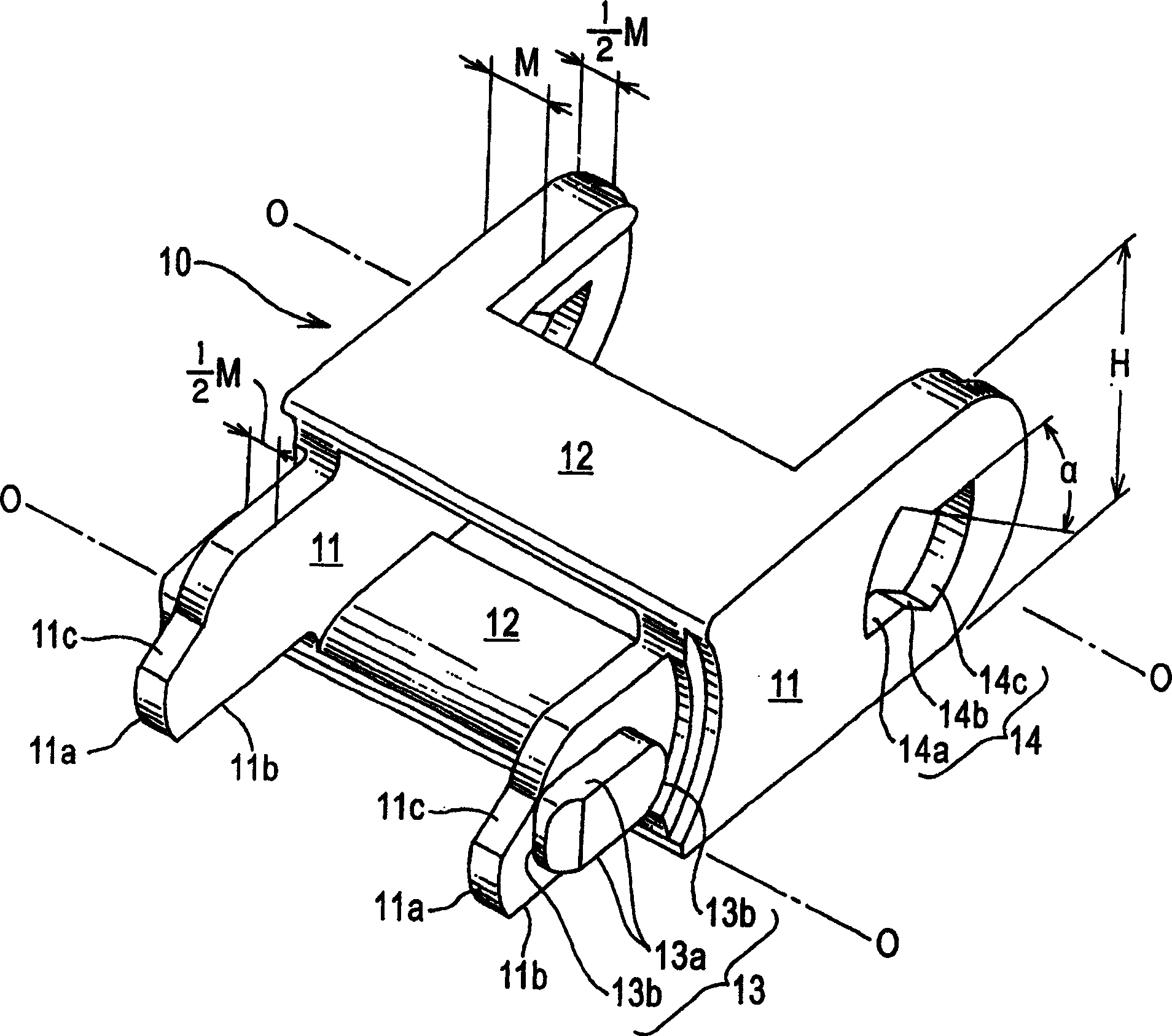
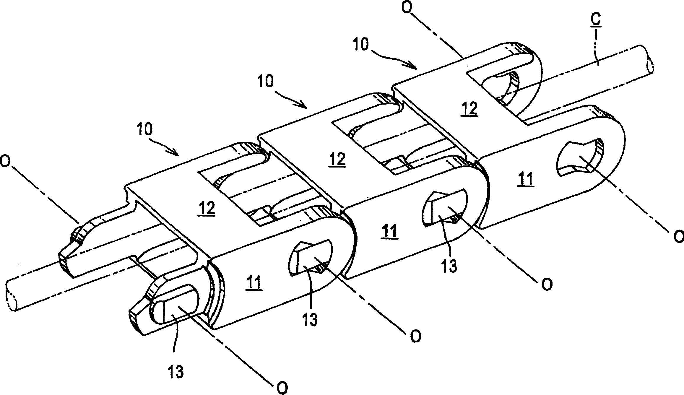
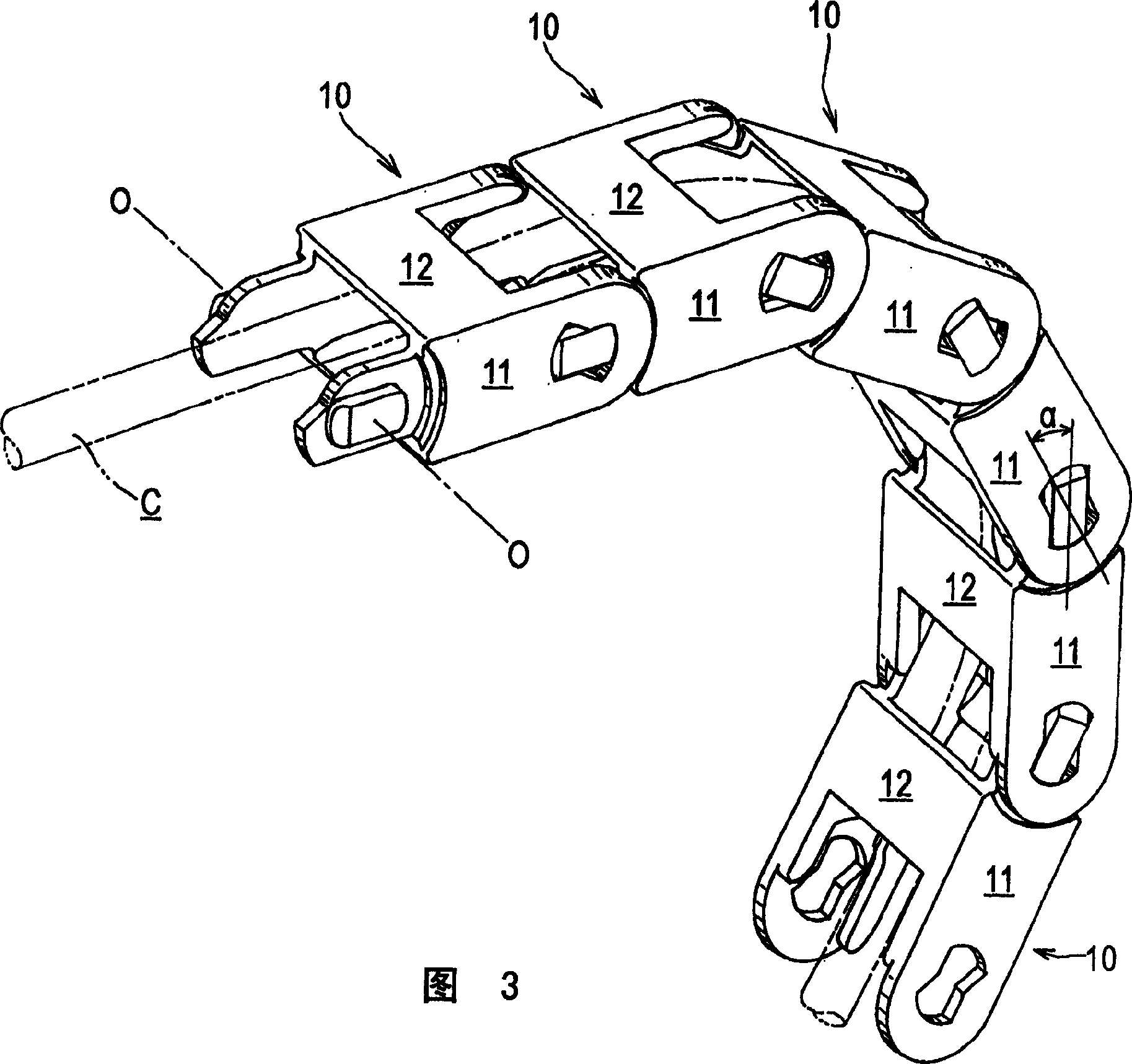
[0027] A protection and guiding device for a cable or the like as an example of the present invention will be described below with reference to the accompanying drawings. figure 1 is an external view of the main body of the link for the protection and guiding device of the cable or the like in the example of the present invention; figure 2 Represent the use mode of the linear position of the protection and guide device of the example cable of the present invention or the like; and Fig. 3 shows the use mode of the bend position of the protection and guide device of the example cable of the invention or the like.

[0028] First, in order to form a cable insertion space for protecting and guiding a cable or the like C including a flexible body such as a cable, a hose or the like, the cable or the like protecting and guiding device of the present invention includes a large number of Rectangular cross-section link bodies 10 hinged to each other, each link body 10 is molded from sy...


PUM


Abstract

Provided is a cable or the like protection and guide device, which can suppress the sliding contact noise by reliably limiting a linear position and a bending position exhibited during the movement of the cable or the like, and at the same time, which can reduce a setting space by suppressing the impact noise and wear of a connecting pin piece on a connecting pin hole even if the height size of the link body is decreased. A connecting pin piece, convexly provided on a link body, which forms a cable or the like protection and guide device, includes stopper surfaces, which are parallel to the upper edge center portion and the lower edge center portion of the side plates and are oppositely disposed across a bending center point and a pair of front, and rear arc-shaped outer circumferential surfaces, which are oppositely disposed across the bending center point. Further a connecting pin hole, concavely provided in said link body, includes a pair of linear position maintaining surfaces, which are parallel to the upper edge center portion and the lower edge center portion of the side plate, and are oppositely disposed across the bending center point, bending position limiting surfaces, which are oppositely disposed across the bending center point in a plane symmetry, and a pair of arc-shaped inner circumferential surfaces oppositely disposed across said bending center point in a plane symmetry to be brought into sliding contact with said connecting pin pieces.

Description

technical field [0001] The present invention relates to a protection and guiding device for cables or the like, which accommodates cables or the like comprising flexible bodies such as cables, hoses or the like for feeding mobile Energy such as electric power, compressed air is supplied, and the device protects and guides the cable or the like stably and reliably even during the movement of the mobile machine. Background technique [0002] As an example of a protecting and guiding device for protecting and guiding a cable or the like including a flexible body such as a cable, a hose or the like, known is a protecting and guiding chain, Wherein the lower ends of a pair of oppositely arranged uprights form a "U" shape in front view by means of a bottom plate, shaft holes are provided in the arc-shaped front of each upright, and a plurality of chain link members are each equipped with a shaft and make the shaft Projecting from the outer side surface of the upright to the arcua...

Claims


Application Information

Patent Timeline
IPC IPC(8): H02G1/06F16G13/16H02G3/30H02G11/00H05K7/00
CPCH02G11/006F16G13/16
Inventor 池田正明小宫庄一郎松田孝之
Owner TSUBAKIMOTO CHAIN CO
Why Eureka
Try Eureka