Multifocal ophthalmic lens with induced aperture

A technology of lenses and spectacle lenses, applied in the field of multifocal eyepieces and lenses

Inactive Publication Date: 2005-02-16
FLORIDA OPTICAL ENG
View PDF10 Cites 18 Cited by
  • Summary
  • Abstract
  • Description
  • Claims
  • Application Information

AI Technical Summary

Problems solved by technology

[0011] Lenses made according to the above patents and methods reflect optical limitations caused

Method used


Image

  • Multifocal ophthalmic lens with induced aperture
  • Multifocal ophthalmic lens with induced aperture
  • Multifocal ophthalmic lens with induced aperture

Examples


Embodiment Construction

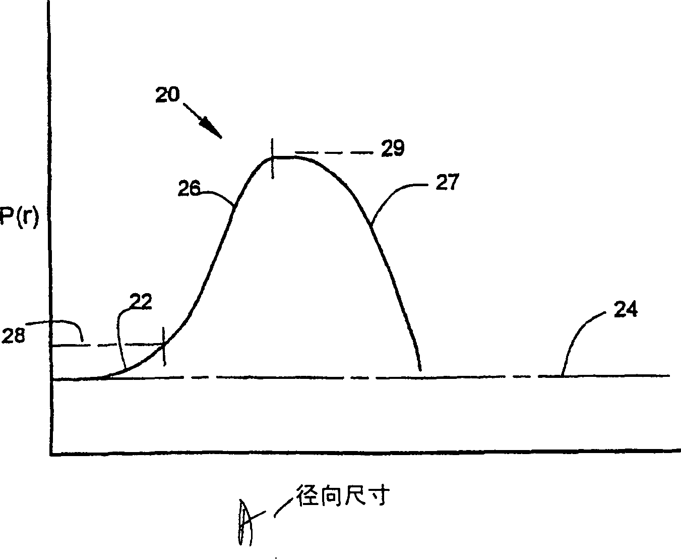
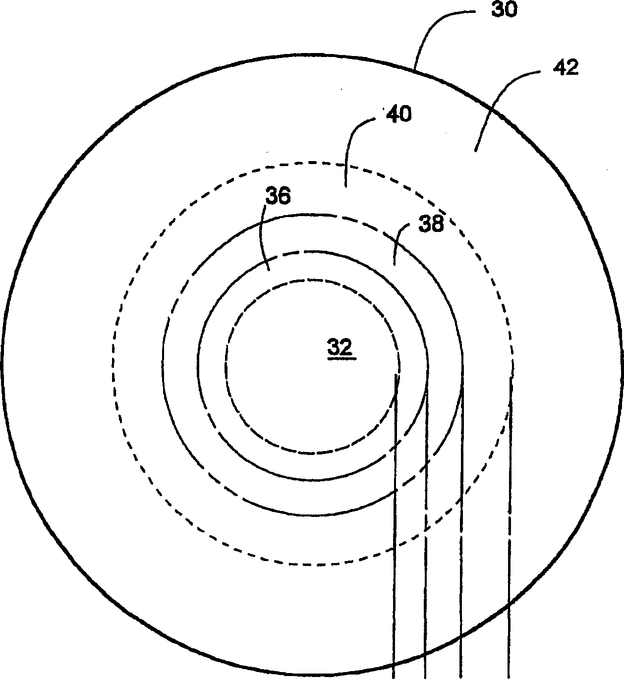
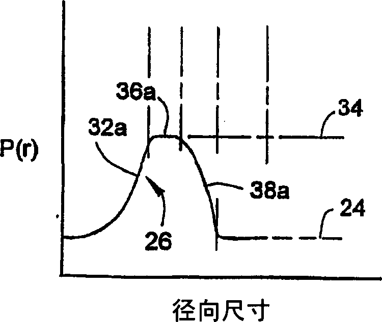
[0026] figure 1 The local light intensity distribution 20 of one embodiment of the invention is depicted as a function of radial dimension from the apex. The vertical axis is the light intensity P(r), while the horizontal axis is the radial dimension from the apex. The centrally located distance vision zone 22 has a distance corrective strength effectively approaching the apex strength 24 . The distance correction strength is the strength required to correct vision when viewing objects at infinity. The desired strength of distance correction can vary according to the specific needs of the user. Optical power gradually increases with increasing radius in the distance vision zone 22 until a design level strength 28 is reached. The increase in intensity from the apex intensity 24 (distance vision intensity) to the intensity that causes blurring when entering the pupil edge is defined here as the design level 28 . Intensity increments that cause blurring in most people were fo...


PUM


Abstract

Multifocal lenses are defined by nonconical aspheric optical surfaces. Various alternative surface shapes provide a central distance vision region surrounded by an optical step. The optical step has repidly increasing power in the radial direction which creates an induced aperture through which the cortical elements of the vision system are induced to concentrate. The induced aperture results in increased clarity in distance vision. Nonconical aspheric optical surfaces are defined to produce the desired optical power distributions. These surface functions are also provided in form of polynomial series for simplicity of use in computer driven lathes for shaping contact lenses. To allow increased manipulation of the defining functions additional elements such as conic terms are added. To improve near vision correction in some configurations, an annular near vision region extends radially outward from the optical step. To improve low light distance vision, power is reduced in the lens region outside the mesopic pupillary dimension. In alternative embodiments, the distance vision region and optical step are formed by cyclic functions. These have benefits in ease of manipulation to fit various specific user geometry requirements. In some configurations, an extended near vision region is used outside the optical step to improve near vision correction. The invention includes contact lenses, scleral lenses, intraocular lenses, and lenses impressed or surgically shaped within the corneal tissue as well as methods of designing and fitting these lenses. Although nominally positive power lenses are also within the present invention, negative lenses gain particular benefit due to decreased lens thickness at the lens perimeter and consequent reduced spherical aberration.

Description

[0001] related application [0002] This application claims priority to US Patent Application No. 09 / 657,562, filed September 8,2000. Background of the invention [0003] The present invention relates to a lens having more than one focal length. The provided methods and structures are applicable to near and spectacle lenses and other lenses used to correct human vision. [0004] Most vision correction lenses are designed to correct distance vision only—that is, have a unique focal length. When a person looks at an approaching object, the eyes adapt to the divergent light emanating from the approaching object rather than parallel light. The accommodation of the human eye results in a physical change in the shape of the lens in the eye. The curvature of the lens reconverges and focuses incident light diverging from approaching objects onto the retina. This accommodation increases the convergence of light waves by bending the lens surface more steeply, which in turn increases ...

Claims


Application Information

Patent Timeline
IPC IPC(8): G02C7/06G02C7/02
CPCG02C7/063G02C7/044G02C7/042G02C7/028G02C7/061A61F2/16A61F2/1618A61F2250/0036A61F2/1613A61F2/164G02C7/041
Inventor 理查德·A·格里芬
Owner FLORIDA OPTICAL ENG
Why Eureka
Try Eureka