Improved LF rotary and strong constant magnet field therapeutical instrument

A treatment device and an improved technology, which is applied in the field of an improved low-frequency rotating strong constant magnetic field treatment device, can solve the problems of large vibration, scattered magnetic field lines of force, and high noise, and achieve the effect of improving sleep density, increasing sleep density, and improving sleep

Inactive Publication Date: 2005-02-23
杭州康尔医药科技有限公司
View PDF3 Cites 21 Cited by
  • Summary
  • Abstract
  • Description
  • Claims
  • Application Information

AI Technical Summary

Problems solved by technology

The reason is that the volume of the permanent magnet is not large enough
Chinese patent 97116885.7, titled "A Gyromagnetic Therapy Bed", provides a bed body with a fixed bed surface and a reciprocating movable bed surface located at the lower part of the fixed bed surface. At least two rotating magnetic machines are installed on the upper end surface. The upper end surface of the magnetic disk of the rotating magnetic machine is adjacent to the bottom of the fixed bed surface. The magnetic force lines generated by the magnetic field provided by this patent are relatively scattered, and the therapeutic effect is limited.
The disadvantage is that the shape of the permanent magnet is mostly a regular trapezoid or rectangle, and the magnetic field strength is greatly affected by the volume, end surface area and magnetic flux change of the permanent magnet, and its effective action depth and effective action range are limited; the mechanical part of the magnetic therapy device The motor is connected with the worm reducer to drive the output shaft to rotate. The structure is complex, the vibration is large and the noise is high during operation, which affects the treatment effect of patients.

Method used


Image

  • Improved LF rotary and strong constant magnet field therapeutical instrument
  • Improved LF rotary and strong constant magnet field therapeutical instrument
  • Improved LF rotary and strong constant magnet field therapeutical instrument

Examples


Embodiment 1

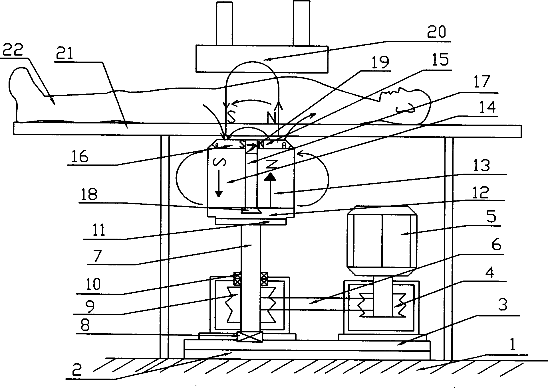
[0027] Such as image 3 As shown, a layer of hard rubber layer 2 and a base plate 3 are placed horizontally on a solid ground 1, and a vertical motor 5 and a drive shaft 7 are fixedly placed on the corresponding brackets of the base plate 3, which can rely on their own The weight is used to balance the shaking generated during the operation of the device; a small pulley 4 is fixed on the 5-axis head of the motor, and is connected to the large pulley 9 of the transmission shaft 7 through the A-type V transmission belt 6. This mechanical part has a simple structure, stable speed, and low noise. Lower; the transmission shaft 7 is placed vertically, two tapered roller bearings 10 of the same type are installed on the upper end of the large pulley, a cylindrical roller bearing 8 is installed on the lower end, and a horizontal flat plate 11 made of magnetic conductive material is connected to the top of the transmission shaft 7 A magnetic yoke 12 made of magnetic material is connect...

Embodiment 2

[0031] Such as Figure 5Shown, on the basis of embodiment 1, pole head 15 is replaced with three-layer pole head 22,23,24, pole head 16 is replaced with three-layer pole head 25,26,27, and pole head 22,25 are glued respectively Knotted on the outer end faces of permanent magnets 13 and 14, pole heads 23, 24 and 26, 27 are respectively fixed on the outer end faces of pole heads 22 and 25 with four screws 28, and pole heads 22, 23, 24 and pole heads 25, 26, 27 have an inclination angle θ on the opposite inner side so that a dovetail-shaped deep groove 18 is formed therebetween. On the partition plate 17 sandwiched between the two permanent magnets 13 and 14, a high-coercivity high-coercivity permanent magnet is bonded. 19. The upper end surface of the high-coercivity permanent magnet 19 is flush with the upper end surfaces of the pole heads 22 and 25, and the upper end surfaces of the high-coercivity permanent magnet 19 are respectively connected with two permanent magnets of hi...


PUM


Abstract

An improved therapeutic appliance with strong and constant low-frequency rotary magnetic field for treating the late bone cancer and osteoporosis is composed of a drive structure consisting of vertical motor, belt, small and big belt wheels, two permanent magnets isolated by non-magnetic partition and a magnetic yoke, and a control unit consisting of infrared remote controller of motor, computer and printer.

Description

technical field [0001] The invention relates to a low-frequency magnetic therapy device, in particular to an improved low-frequency rotating strong constant magnetic field therapy device. Background technique [0002] Studies have found that the magnetic field has a significant impact on the human body and other organisms, water or chemical agents. At present, most of the rotating magnetic fields provided by permanent magnets adopt a pair of poles or multiple pairs of poles. in the middle of the permanent magnet. The magnetic field generated by the permanent magnet placed in the above way (such as figure 1 , 2 As shown) the magnetic field permeates the inside of the magnet, or the magnetic field can only act on the outer surface. The reasons are: first, there is no change in the magnetic field, and the effect on the magnet is small; Carry out strong magnetic field treatment; The third is that the permanent magnet produces magnetic field lines to ...

Claims


Application Information

Patent Timeline
Patent Type & Authority Applications(China)
IPC IPC(8): A61N2/12
Inventor 张小云
Owner 杭州康尔医药科技有限公司
Why Eureka
Try Eureka