
Multiple shaft multiple rotor dynamic balancing test method

A test method and multi-rotor technology, applied in the field of dynamic balance test, to achieve the effect of high technical value, practical value and high balance accuracy

Inactive Publication Date: 2005-03-02
HENAN UNIV OF SCI & TECH
View PDF0 Cites 9 Cited by
  • Summary
  • Abstract
  • Description
  • Claims
  • Application Information

AI Technical Summary

Problems solved by technology

[0003] In order to solve the problem of multi-axis and multi-rotor dynamic balance, the present invention provides a multi-axis and multi-rotor dynamic balance test method to solve the problem of multi-axis and multi-rotor dynamic balance and improve the performance of multi-axis and multi-rotor dynamic balance test. precision

Method used


Image

  • Multiple shaft multiple rotor dynamic balancing test method
  • Multiple shaft multiple rotor dynamic balancing test method
  • Multiple shaft multiple rotor dynamic balancing test method

Examples


Embodiment Construction

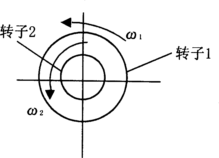
[0029] for figure 1 For the dual-rotor system shown, before assembly, the rotor 1 and the rotor 2 are subjected to a dynamic balance test respectively, so that the balance error is within the range specified by the relevant standards. After assembly,

[0030] The vibration vector of rotor 1 is A 11 =A 11 e φ11

[0031] The vibration vector of rotor 2 is A 21 =A 21 e φ21

[0032] Taking rotor 1 as the measurement reference, make rotor 1 and rotor 2 rotate at the same time, extract the unbalance signal of the whole centrifuge, when the period p=5, for the centrifuge

[0033] because Σ i = 1 4 A 2 i e φ 2 i = 0

[0034] Σ i = 1 ...


PUM


Abstract

The invention relates to an experimental method for multi axis series and multi rotor dynamic balance, includes the following steps(1) before assembly, do assembly experiment to each fiducial respectively, making balanced error within standard specialized range; (2) each fiducial is assembled; (3) choose willingly one rotor to be the measuring basis and make complete machine revolve according to working condition, then extract inbalanced signal of P vibration periods in the system (P is the smallest common multiple or its integral multiple of vibration periods of all rotor in the system ) and do dynamic balance to the fiducial rotor; (4) choose willingly another rotor as measuring basis choose willingly one rotor to be the measuring basis and make the complete machine revolve according to working condition, then extract inbalanced signal of P in the system (P is the smallest common multiple or its integral multiple of vibration periods of all rotor in the system ) and do dynamic balance to the fiducial rotor; (5) repeate step(4) until all the rotors have been dynamic balanced, the complete machine experiment is finished.

Description

technical field [0001] The invention relates to a dynamic balance test method, in particular to a test method capable of performing dynamic balance of multi-shaft systems and multi-rotors. Background technique [0002] With the development of modern machine products in the direction of high speed and high precision, the requirements for the dynamic balance quality of machine products are also increasing. For many machines, not only the parts need to be precisely balanced during the manufacturing process, but also the on-site monitoring of the production and running status and the on-site dynamic balancing of the whole machine are required. Dynamic balancing technology has developed many mature technologies and methods since its birth. However, these technologies and methods are all aimed at single shaft and single speed. Using existing technologies and methods to dynamically balance multi-axis and multi-speed equipment is not only laborious and time-consuming, but also imp...

Claims


Application Information

Patent Timeline
Patent Type & Authority Applications(China)
IPC IPC(8): G01M1/16H02K15/16
Inventor 李济顺马伟郑国强贾现召短明德李航
Owner HENAN UNIV OF SCI & TECH
Learn More