
Driving protective circuit for inverse resistance type insulated gate bipolar transistor

A technology of bipolar transistors and drive protection circuits, which is applied in the field of drive protection circuits and can solve problems such as damage to drive power supplies, burned devices, and inapplicable overcurrent protection functions.

Inactive Publication Date: 2005-03-02
TSINGHUA UNIV
View PDF0 Cites 51 Cited by
  • Summary
  • Abstract
  • Description
  • Claims
  • Application Information

AI Technical Summary

Problems solved by technology

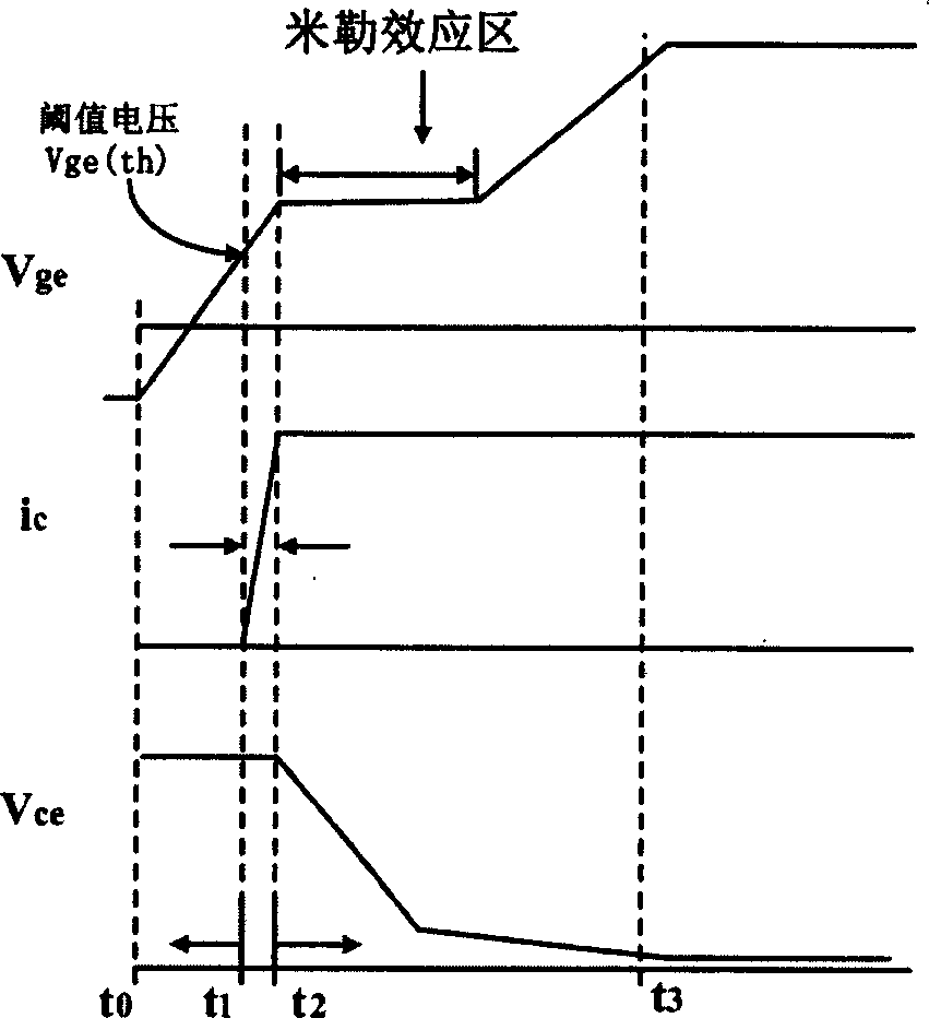
[0012] (3)t 6 After time, V ge continues to decrease, causing the collector current i c decrease
[0017] However RB-IGBT has no anti-parallel diode, V ce The positive and negative working limits are equal. It can be seen that if the current connection method of the integrated drive chip protection circuit is used, D101 will directly introduce negative high voltage into the drive circuit, causing damage to the drive power supply, or even burning the device.
Therefore, the overcurrent protection function in the current mature IGBT driver chip is not suitable for RB-IGBT

Method used


Image

  • Driving protective circuit for inverse resistance type insulated gate bipolar transistor
  • Driving protective circuit for inverse resistance type insulated gate bipolar transistor
  • Driving protective circuit for inverse resistance type insulated gate bipolar transistor

Examples


Embodiment Construction

[0064] The principle circuit of the three-stage drive circuit proposed by the present invention is as follows: Figure 7 shown.

[0065] On the traditional push-pull structure (Q1, Q2, R7, R8), add two dynamic charging and discharging current sources (M1, M2, D1, D3, R1, R3, R5 constitute the charging current source of the opening process; M3, M4, D2, D4, R2, R4, R6 constitute the discharge current source of the shutdown process). The control circuit is realized by the programmable digital logic chip GAL and the detection circuit.

[0066] Device selection: M1 uses N-channel MOSFET 2N7000, with a typical on-off time of 10ns; M2 uses P-channel MOSFET IRFR5505. Turn-on delay + rise time 40ns, turn-off delay + fall time 36ns. M3 uses a P-channel FET VP0300. Typical turn-on and turn-off time is 30ns; M4 uses N-channel MOSFET IRFR220. Turn-on delay + rise time 30ns, turn-off delay + fall time 32ns. The current source control logic uses GAL16v8D-25LP, with a typical delay of 2...


PUM


Abstract

This invented driving protection circuit for inverse impadance insulated-gate bipolar transistor is composed of: (1). a controller; (2). a three-section driving circuit, comprising a dynamic charging current source, a dynamic discharging current source a push-pull amplifier circuit series connected with them; (3). a detecting circuit, when the device being of power-on, it cotnrols the rising-rate of the current at the collector; on the other hand, when power-off, it controls the rising-rate of the voltage at the collector; and (4). a RB-IGBT over-current protection circuit for V(Ce) detection, being connected to the collector of said inverse impadance insulated-gate bipolar transistor. It has two V(Ce) detection schemes.

Description

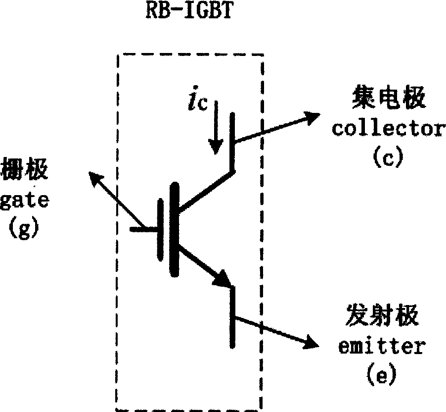
technical field [0001] The invention belongs to the drive protection circuit of the reverse resistance type insulated gate bipolar transistor, and belongs to the technical field of RB-IGBT control. Background technique [0002] Reverse Blocking Insulated Gate Bipolar Transistor (Reverse Blocking Insulated Gate Bipolar Transistor), referred to as RB-IGBT, is a new type of power semiconductor device. Compared with ordinary IGBT devices, it has the forward and reverse blocking ability of voltage. RB-IGBT can be used to form a bidirectional switch to realize bidirectional flow of energy, and is currently mainly used in matrix converters. figure 1 The bidirectional switch structure using RB-IGBT and ordinary IGBT is given. It can be seen that the bidirectional switch using RB-IGBT requires the least power devices. At the same time, the voltage drop on the bidirectional switch using RB-IGBT is much smaller than that of ordinary IGBT bidirectional switch in steady state, so the ...

Claims


Application Information

Patent Timeline
IPC IPC(8): H02H7/122H03K17/08
Inventor 周大宁刘智超黄立培
Owner TSINGHUA UNIV
Learn More