Image recording apparatus

一种图像记录、记录材料的技术,应用在图纹面的照相制版工艺、光学、仪器等方向,能够解决很难高度准确的旋转记录鼓、不容易冲孔单元定制等问题,达到提高准确度的效果

Inactive Publication Date: 2005-03-09
DAINIPPON SCREEN MTG CO LTD
View PDF2 Cites 2 Cited by
  • Summary
  • Abstract
  • Description
  • Claims
  • Application Information

AI Technical Summary

Problems solved by technology

When the recording drum is rotating at high speed, due to the weight of the punching unit, it will be difficult to rotate the recording drum with high accuracy unless the weight balance of the entire recording drum is adjusted very accurately
When the punching unit is customized, weight balance adjustment must be performed on the recording drum again, so its disadvantage is that it is not easy to customize the punching unit

Method used


Image

  • Image recording apparatus
  • Image recording apparatus
  • Image recording apparatus

Examples


Embodiment Construction

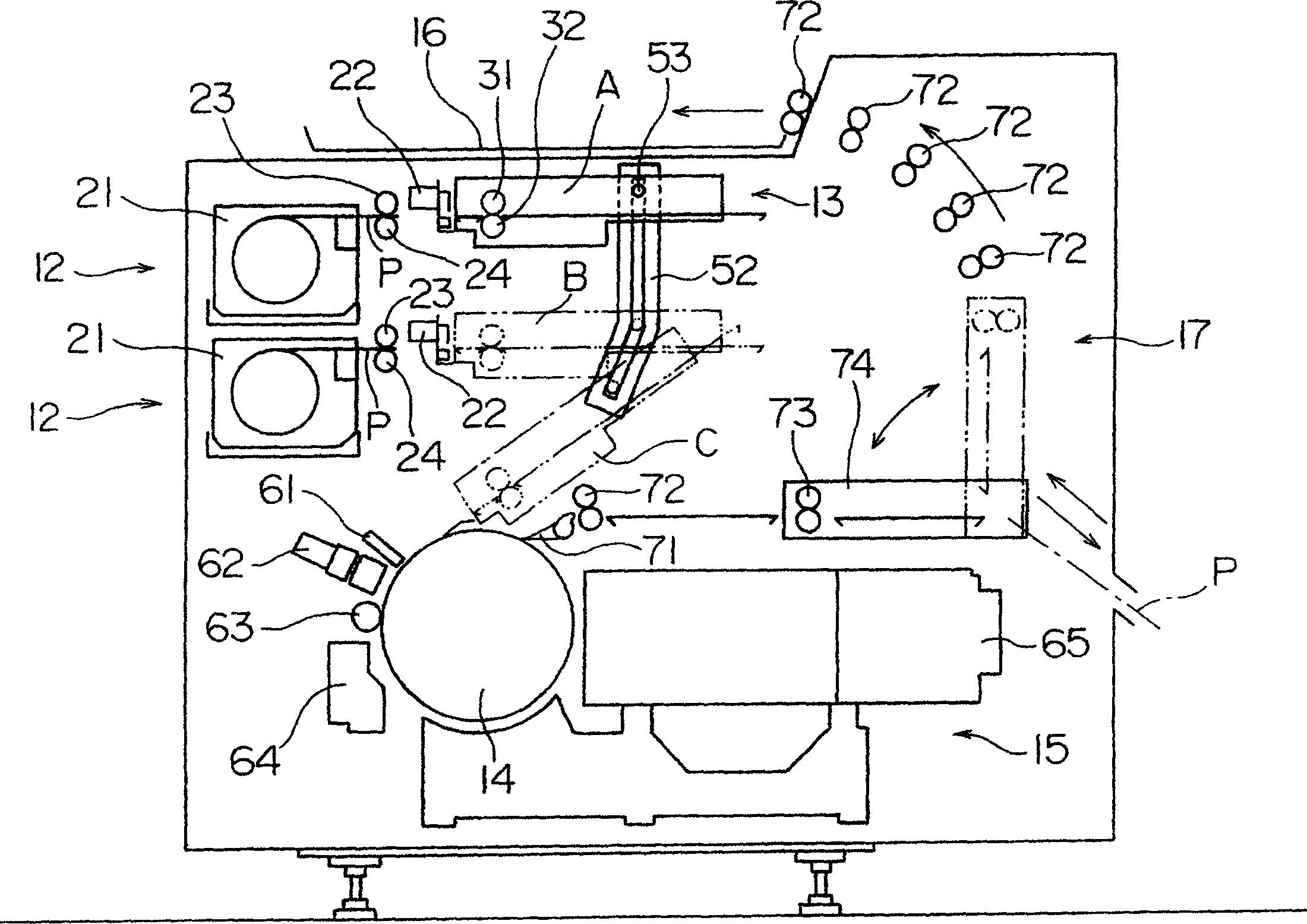
[0044] The present invention will be described below with reference to the accompanying drawings. figure 1 is a schematic diagram of an image recording apparatus according to the present invention.

[0045] This image recording apparatus includes two recording material storage sections 12 arranged vertically; a recording material conveying device 13 for conveying recording materials P; a lifting mechanism for raising and lowering the conveying device 13; having a cam 52 and a cam follower 53 for tilting the conveying device 13; the recording drum 14 for supporting the recording material P mounted on its periphery; the image recorder 15 for recording an image on the recording material P mounted on the recording drum 14; and a release mechanism 17 for releasing the image-recorded recording material P onto the release tray 16 .

[0046] Each recording material storage section 12 includes a feed cassette 21 in which an elongated recording material P in a curled form is stored, an...


PUM


Abstract

A punch unit includes punch blocks supported by an arm through support plates. The arm has, arranged thereon, a motor for rotating a drive rod (105), a detector for detecting rotation angles of the drive rod, and a sensor for detecting a forward end of a recording material. The punch unit is movable by a moving mechanism including support members arranged at opposite ends of the arm, slide shafts and ball screws connected to the support members, and a pulse motor for driving the ball screws through a synchronous belt and synchronous pulleys.

Description

technical field [0001] The present invention relates to an image recording apparatus for recording an image by emitting a light beam to a recording material mounted on a recording drum. Background technique [0002] When printing with four color inks, such as yellow (Y), purple (M), cyan (C), and black (B) inks, the positioning holes for the printing machine used to position the printing plate and the printing plate Between recorded images, the same positional relationship must be maintained for each of the YMCK colors. As used in this specification, the term "pilot hole for a printing press" includes a pilot hole for placing a printing plate on the plate cylinder of a printing press, as well as a punched hole, such as a pilot hole, for placing a printing plate Place on the punch to create another punched hole in the printed board. [0003] In the method proposed in USP6213020 (hereinafter referred to as "the first method"), before the recording material is attached to the...

Claims


Application Information

Patent Timeline
Patent Type & Authority Applications(China)
IPC IPC(8): G03F9/00B41C1/10
CPCB41C1/1083
Inventor 田村利夫川田亨田中宏尚奥胜次
Owner DAINIPPON SCREEN MTG CO LTD
Why Eureka
Try Eureka