Catelectrode atomization type preweld cleaning equipment for aluminum alloy welding wire

A technology of aluminum alloy welding wire and cathode atomization, applied in welding equipment, arc welding equipment, metal processing equipment, etc., can solve the problems of incomplete processing of aluminum alloy welding wire, difficult welding process, and combination

Inactive Publication Date: 2005-03-16
HARBIN INST OF TECH
View PDF0 Cites 9 Cited by
  • Summary
  • Abstract
  • Description
  • Claims
  • Application Information

AI Technical Summary

Problems solved by technology

[0003] In order to overcome the defects of the existing technology or the incomplete treatment of aluminum alloy welding wire or the difficulty in combining it with the welding process, a pre-welding aluminum alloy welding wire that can completely remove the oxides on the surface of the aluminum alloy welding wire and can be used in combination with the welding process is provided. cleaning equipment

Method used


Image

  • Catelectrode atomization type preweld cleaning equipment for aluminum alloy welding wire
  • Catelectrode atomization type preweld cleaning equipment for aluminum alloy welding wire
  • Catelectrode atomization type preweld cleaning equipment for aluminum alloy welding wire

Examples


specific Embodiment approach 1

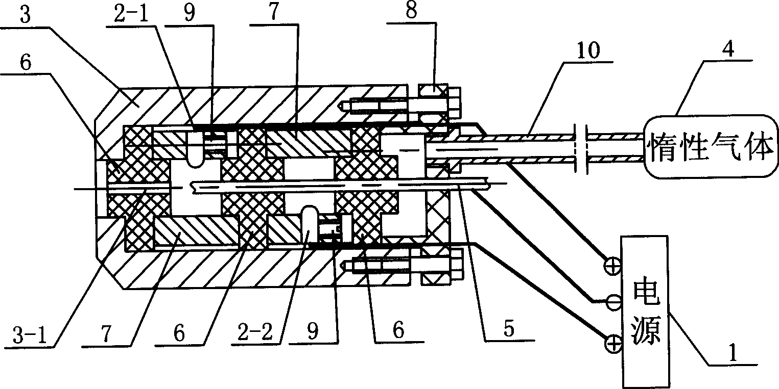
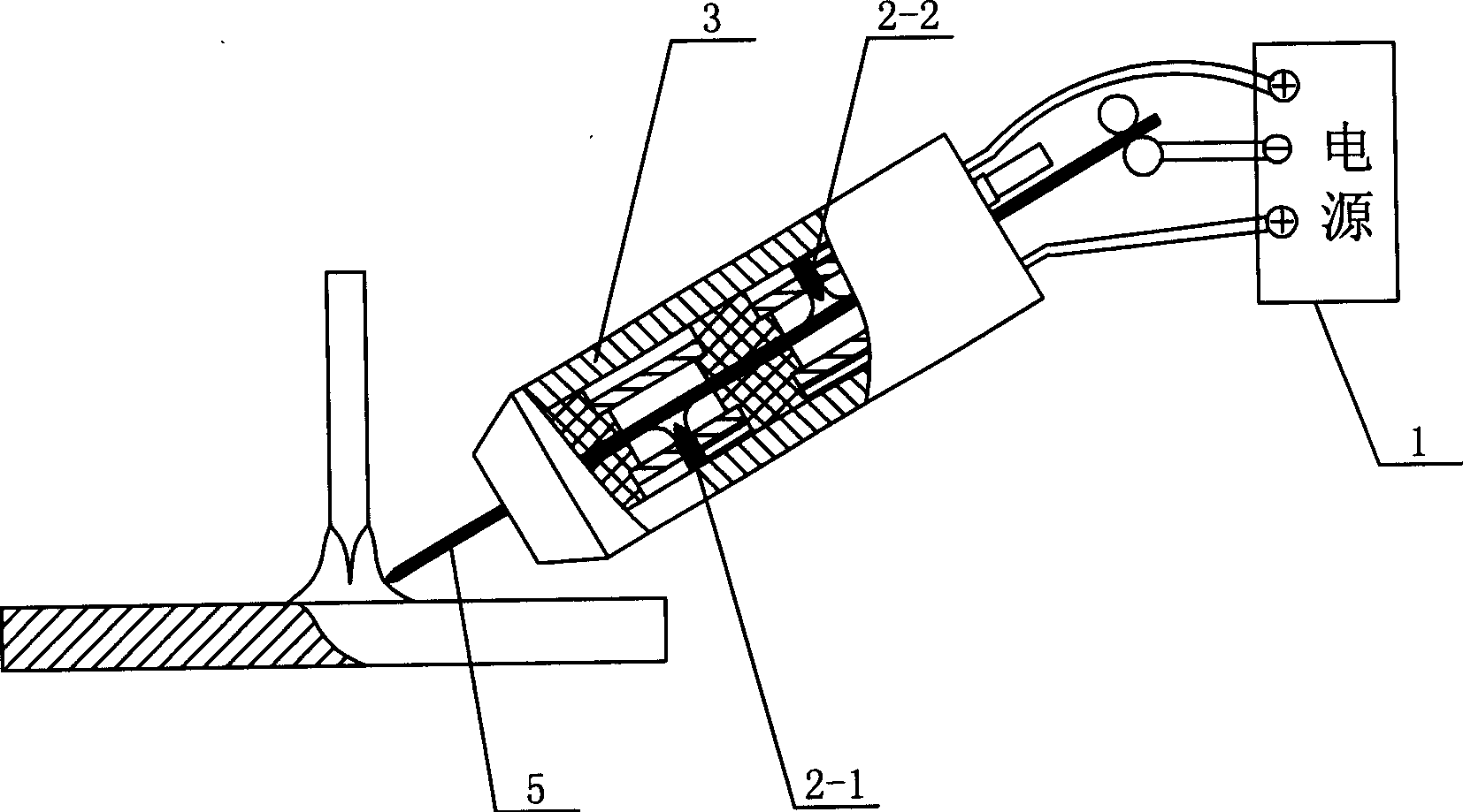
[0005] Specific implementation mode one: the following combination figure 1 and figure 2 This embodiment will be specifically described. It consists of a power supply 1, two tungsten electrodes, a pipeline 10, a shell 3 and an inert gas container 4, and the closed shell 3 has a thread-through hole 3-1, the first tungsten electrode 2-1 and the second tungsten electrode 2-2 is arranged in the inner cavity of the housing 3 and arranged on both sides of the threading hole 3-1, the first tungsten electrode 2-1 and the second tungsten electrode 2-2 are arranged in the axial direction of the threading hole 3-1. Stagger the distance and connect with the anode output end of the power supply 1 respectively, the inner chamber of the casing 3 communicates with the inert gas container 4 through the pipeline 10, and the welding wire to be processed is connected with the cathode of the power supply.

specific Embodiment approach 2

[0006] Specific implementation mode two: the following combination figure 1 This embodiment will be specifically described. The difference between this embodiment and the first embodiment is that it also includes three spacers 6, two positioning sleeves 7 and a gland 8, and the spacers 6 and positioning sleeves 7 are sealed in the inner cavity of the housing 3 by the gland 8 Among them, two positioning sleeves 7 separate the three spacers 6, and the first tungsten electrode 2-1 and the second tungsten electrode 2-2 are fixed on the positioning sleeve 7 by screws 9. With such arrangement, it is very convenient to assemble and disassemble the tungsten electrode, which makes the work of adjusting and repairing the tungsten electrode easy.

specific Embodiment approach 3

[0007] Specific implementation mode three: the following combination image 3 This embodiment will be specifically described. The difference between this embodiment and the first embodiment is that the first tungsten electrode 2-1 and the second tungsten electrode 2-2 can be ring electrodes according to specific needs.


PUM


Abstract

The invention makes public a kind of negative electrode atomization cleaning device which is used to clean the aluminum alloy welding thread before welding. The device consists of current source, at least two tungsten electrodes, tube, shell body, and inert gas container. Through the sealed body is thread bore. And the two electrodes are inside the body, separate each other above the thread bore and connect respectively to positive outing end. Lumen of the body connects to the inert gas container by tube. The two tungsten electrodes strike fire respectively with aluminum alloy welding thread and produce mini electric arc to clean the oxidation film covering the welding thread. The invention uses the negative atomization phenomenon of aluminum alloy welding to clean the welding thread before melting it by mini arc. The invention is a cleaning method going with welding, can clean more completely than previous method. It also can heat the welding thread in advance so can improve the welding efficiency.

Description

Technical field: [0001] The invention relates to a pre-weld cleaning device for aluminum alloy welding wire. Background technique: [0002] In aluminum alloy welding, the oxide film on the surface of the alloy (Al 2 o 3 ) absorb a large amount of oil and water, and the introduction of these impurities will have a great impact on the weld performance of aluminum alloys, especially the problem of hydrogen pores in the weld. The solubility curve of aluminum alloy to hydrogen (approximately 0.69ml / 100g in the liquid state, and suddenly drops to 0.036ml / 100g in the solid state) determines that there are inevitably hydrogen pores in the aluminum alloy welding seam, and the hydrogen source (such as: H 2 O) Once it enters the welding atmosphere, it is difficult to be removed and eventually becomes a hydrogen hole in the weld. On the other hand, when aluminum alloy is welded, due to its oxide film (Al 2 o 3 ) melting point (about 2050°C) is much higher than the melting point of ...

Claims


Application Information

Patent Timeline
Patent Type & Authority Applications(China)
IPC IPC(8): B23K9/235
Inventor 杨春利邱灵林三宝伍昀
Owner HARBIN INST OF TECH
Why Eureka
Try Eureka