Scrubber and exhaust gas treatment apparatus

a technology of exhaust gas treatment and scrubber, which is applied in the direction of lighting and heating apparatus, heating types, separation processes, etc., can solve the problems of low dust removal efficiency, mist collector, and exhaust gas containing such silane and halogen gases not being released to the atmospher

Inactive Publication Date: 2003-09-04
EBARA CORP
View PDF9 Cites 17 Cited by
  • Summary
  • Abstract
  • Description
  • Claims
  • Application Information

AI Technical Summary

Problems solved by technology

Since the silane and halogen gases are harmful, combustible, or hardly decomposable, the exhaust gas containing such silane and halogen gases cannot be released to the atmosphere as it is.
1) When the exhaust gas containing silane gas (SiH.sub.4) or the like is heated, oxidized and decomposed in the exhaust gas treatment apparatus 61, the treated exhaust gas contains fine dust having a diameter of 1 .mu.m or less at a high concentration. If the exhaust gas containing such fine dust is scrubbed by the above conventional scrubber, then the dust is removed by a percentage ranging from 20 to 60%, which is a low dust-removal efficiency.
2) In many cases, the conventional mist collector comprises a filling material (SUS, ceramic, plastic, or the like), a metal mesh, a filter, and the like. Since the mist collector has small openings for passing the exhaust gas therethrough, the mist collector tends to be easily clogged by the mist. Consequently, it is necessary to carry out time-consuming cleaning of the mist collector. Further, because a saturated vapor contained in the exhaust gas cannot be trapped by the mist collector, when a temperature of the exhaust gas is lowered after the exhaust gas is passed through the mist collector, the saturated vapor that has passed through the mist collector is changed into mist, thus causing a pipe provided at the downstream side of the mist collector to be clogged by the mist.
However, the gas to be treated and water contained in the cleaning liquid attached to the exhaust gas inlet react with each other to produce SiO.sub.2, thus causing the exhaust gas inlet to be clogged.
However, in the case where the restrictor is provided at the exhaust gas outlet side, the restrictor tends to be clogged due to deposition of dust thereon.
From such viewpoints, it is problematic to employ these methods.

Method used


Image

  • Scrubber and exhaust gas treatment apparatus
  • Scrubber and exhaust gas treatment apparatus
  • Scrubber and exhaust gas treatment apparatus

Examples


first embodiment

[0052] the present invention will hereinafter be described with reference to the drawings.

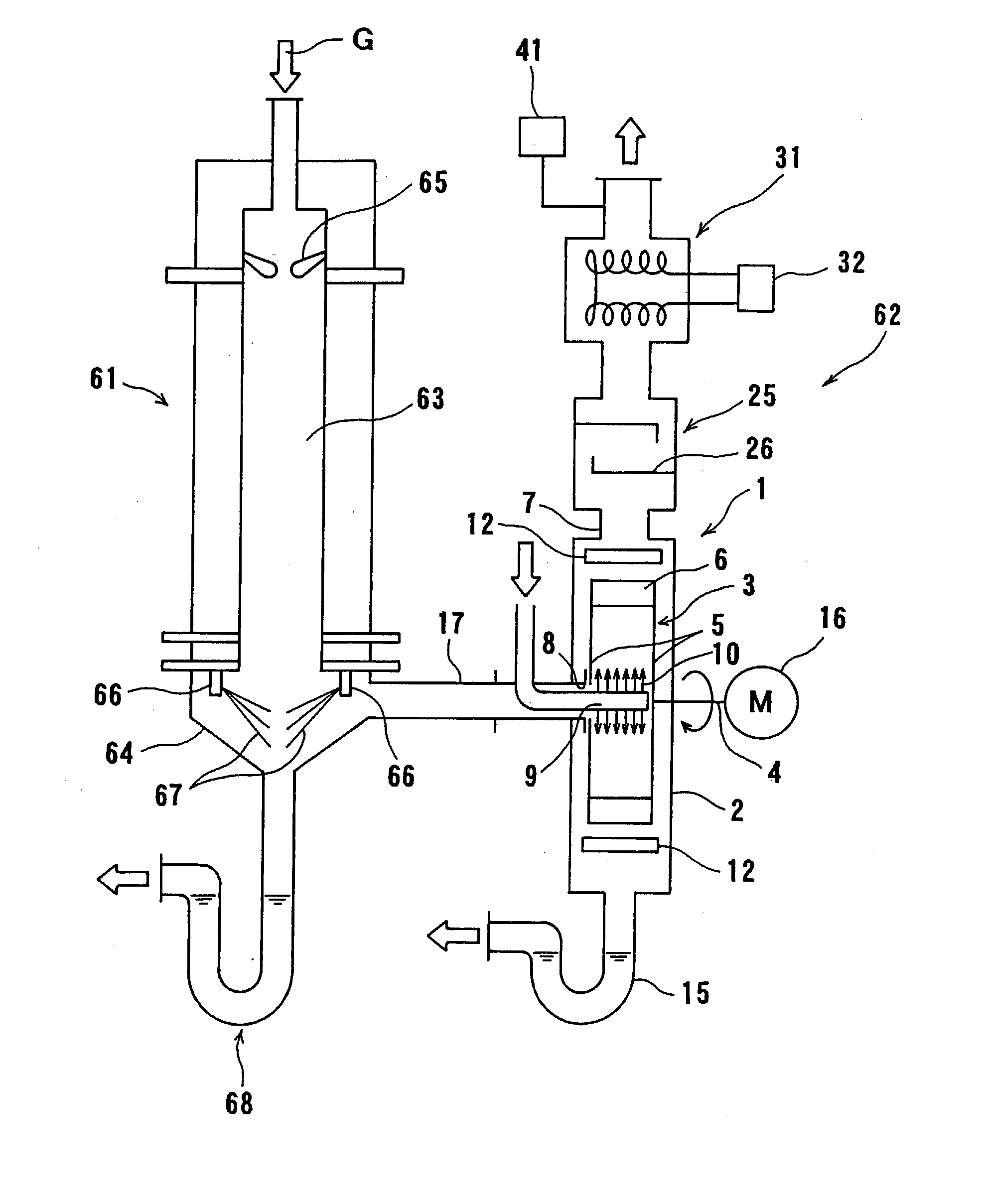
[0053] As shown in FIG. 1, according to a first embodiment of the present invention, an exhaust gas treatment system comprises an exhaust gas treatment apparatus 61, and an exhaust gas treatment apparatus 62 disposed downstream of the exhaust gas treatment apparatus 61. The exhaust gas treatment apparatus 61 comprises a burner 63 for combusting an exhaust gas, and a liquid atomizing area 64 for cooling the exhaust gas which has been combusted by the burner 63. The exhaust gas treatment apparatus 62 comprises a scrubber 1, a mist collector 25, a heat exchanger 31, and a dilution gas supply device 41. An exhaust gas discharged from a semiconductor fabrication apparatus or the like is introduced into the exhaust gas treatment apparatus 61 in the direction indicated by the arrow G. The exhaust gas fed to the burner 63 is combusted by flames 65 generated in the burner 63 for thereby being heated, ox...

sixth embodiment

[0077] A scrubber according to the present invention will be described below with reference to FIG. 10.

[0078] As shown in FIG. 10, the exhaust gas pipe 17 has a slope inclining downwardly toward the exhaust gas inlet 8 at an angle .theta. to horizontal which preferably ranges from 0.2 to 60.degree. C. In the same manner as the first embodiment, the cleaning liquid supply tube 9 extending into the impeller 3 for ejecting the cleaning liquid 10 is disposed in the exhaust gas pipe 17. The cleaning liquid supply tube 9 has a plurality of ejection ports (not shown) positioned inside of the impeller 3, and the cleaning liquid 10 is ejected through the ejection ports. A cleaning nozzle 53 having cleaning liquid ejection ports 53a for intermittently ejecting a cleaning liquid 54 such as water into the exhaust gas pipe 17 is provided in the exhaust gas pipe 17 at the upstream side of the cleaning liquid supply tube 9. Other structural details of the scrubber according to the present embodime...

ninth embodiment

[0089] it is possible to adjust the suction pressure developed by the rotation of the impeller 3 by changing the clearance F. Specifically, if the suction pressure is high, then the clearance F is increased, and if the suction pressure is low, then the clearance F is reduced to adjust the liquid level 68b of the drain pipe 68 (see FIG. 17). Therefore, the liquid 68c in the drain pipe 68 can be maintained at a proper liquid level without changing the operating condition (the rotational speed) of the motor 16 (see FIG. 1), and hence the exhaust gas can be treated without reducing a treatment capability of the scrubber 1.

[0090] A scrubber according to a tenth embodiment of the present invention will be described below with reference to FIG. 15. Structural and operational details of the scrubber according to the tenth embodiment which will not be described below are identical to those of the scrubber according to the first embodiment.

[0091] As shown in FIG. 15, a cylindrical exhaust ga...


PUM

PropertyMeasurementUnit
diameteraaaaaaaaaa
transparentaaaaaaaaaa
temperatureaaaaaaaaaa

Abstract

A scrubber removes dust from an exhaust gas. The scrubber includes a casing having an exhaust gas inlet and an exhaust gas outlet, an impeller housed in the casing and supported by a shaft, and a cleaning liquid supply tube for ejecting a cleaning liquid by which the dust contained in the exhaust gas is captured. The scrubber further includes a plurality of protrusions provided around the impeller such that the exhaust gas and the cleaning liquid which are discharged from the impeller impinge upon the protrusions.

Description

[0001] 1. Field of the Invention:[0002] The present invention relates to a scrubber and an exhaust gas treatment apparatus for removing dust from an exhaust gas, and more particularly to a scrubber for removing dust from an exhaust gas at a high efficiency, and an exhaust gas treatment apparatus having such a scrubber, a heat exchanger disposed at the downstream side of the scrubber, and other equipment.[0003] 2. Description of the Related Art:[0004] In a semiconductor fabrication process and a liquid crystal panel fabrication process, an exhaust gas containing silane gas (SiH.sub.4) or halogen gas (NF.sub.3, ClF.sub.3, SF.sub.6, CHF.sub.3, C.sub.2F.sub.6, CF.sub.4, or the like) is discharged from fabrication apparatuses in the semiconductor fabrication process and the liquid crystal panel fabrication process. Since the silane and halogen gases are harmful, combustible, or hardly decomposable, the exhaust gas containing such silane and halogen gases cannot be released to the atmosph...

Claims


Application Information

Patent Timeline
Patent Type & Authority Applications(United States)
IPC IPC(8): B01D47/06F23J15/04B01D47/08B01D47/18F23J15/02
CPCB01D47/08F23J2217/50F23J15/022B01D47/18B01D53/78F23J15/02
Inventor OKUDA, KAZUTAKAKAWAMURA, KOTARO
Owner EBARA CORP
Why Eureka
Try Eureka