Microdriving fully decoupled macrol/micre bidriving minitype robot moving locating platform
A technology for mobile positioning and positioning platform, applied in micro manipulators, instruments, manipulators, etc., can solve the problems of slow speed, high speed, and inability to complete micro-operation tasks with high efficiency and high quality.
- Summary
- Abstract
- Description
- Claims
- Application Information
AI Technical Summary
Problems solved by technology
Method used
Image
Examples
specific Embodiment approach 1
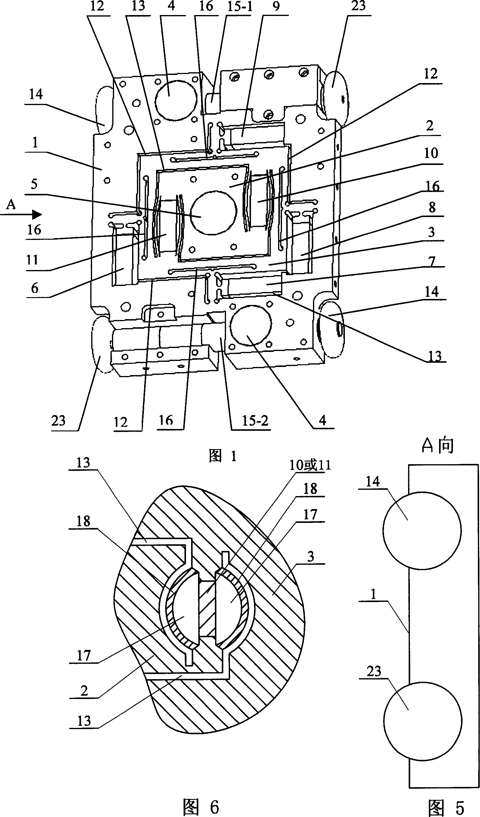
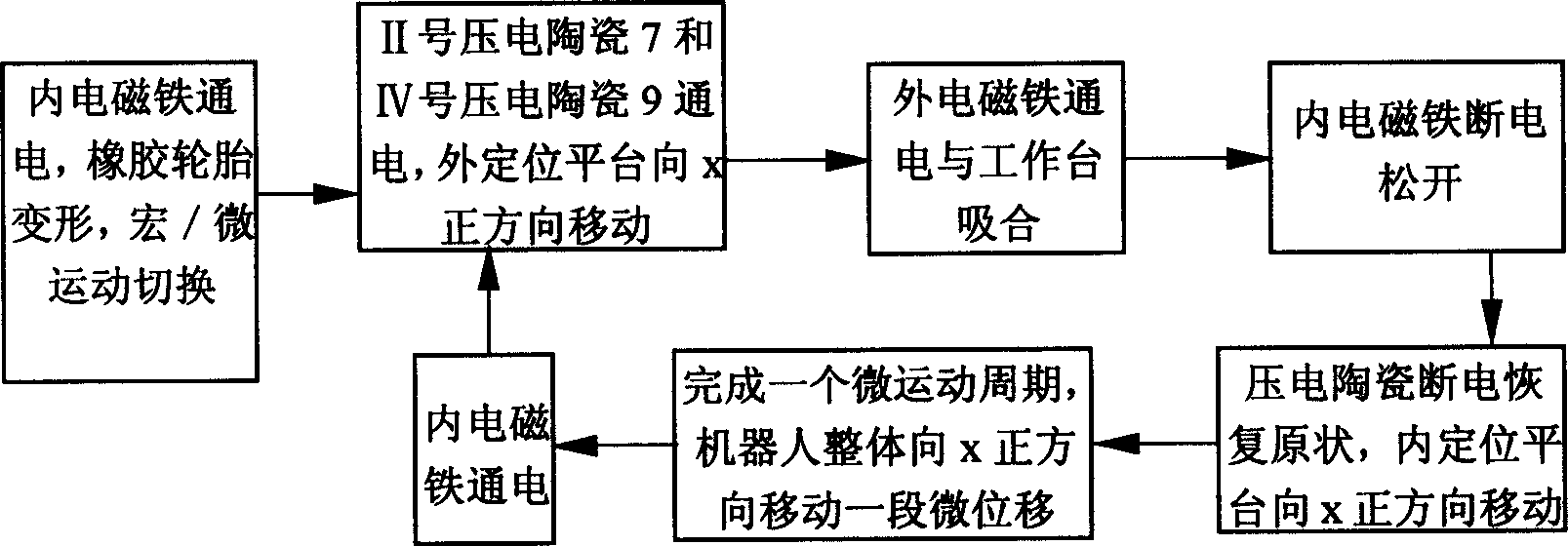
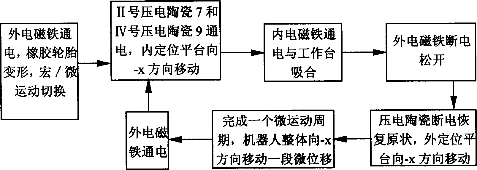
[0005] Specific implementation mode 1: This implementation mode will be specifically described below with reference to FIG. 1 and FIG. 5 . It consists of macro motion mechanism, outer positioning platform 1, inner positioning platform 2, transition platform 3, outer electromagnet 4, inner electromagnet 5, I piezoelectric ceramic 6, II piezoelectric ceramic 7, III piezoelectric ceramic 8, Composed of No. IV piezoelectric ceramic 9, No. V piezoelectric ceramic 10, and No. VI piezoelectric ceramic 11, there is an outer ring flexible hinge groove 12 between the outer positioning platform 1 and the transition platform 3, and the transition platform 3 and the inner positioning platform 2 There is an inner ring flexible hinge groove 13 between them, the outer electromagnet 4 is arranged on the outer positioning platform 1, the inner electromagnet 5 is arranged in the middle of the inner positioning platform 2, and No. I piezoelectric ceramics 6, No. II piezoelectric ceramics 7, III N...
specific Embodiment approach 2
[0006] Specific Embodiment 2: The present embodiment will be specifically described below with reference to FIG. 1 and FIG. 5 . The difference between this embodiment and Embodiment 1 is that the macro motion mechanism is composed of two driving wheels 23, two driven wheels 14, a motor 15-1 and a motor 15-2, and the two driving wheels 23 are respectively arranged on the outer positioning platform 1 Two driven wheels 14 are respectively arranged at another group of diagonal corners of the outer positioning platform 1, and the motor 15-1 and the motor 15-2 provide rotational power to the driving wheel 23. The rim outer surfaces of the two driving wheels 23 and the two driven wheels 14 are made of rubber. With such arrangement, when the electromagnet is electrified and attracted to the ferromagnetic workbench, the rubber is deformed so that the outer positioning platform 1 or the inner positioning platform 2 does not move. The micro-robot mobile positioning platform has the foll...
specific Embodiment approach 3
[0007] Specific Embodiment Three: The present embodiment will be specifically described below with reference to FIG. 1 . The difference between this embodiment and Embodiment 1 is that it also includes four strip-shaped flexible hinge slots 16, which are respectively opened on the four frame sides of the transition platform 3 and arranged along the length direction of the frame sides. Such setting can improve the deformation and movement ability of the platform of the present invention when it moves slightly, and improve the flexibility. Other components and connections are the same as those in Embodiment 1.
PUM
 Abstract
Description
Claims
Application Information
 - R&D
- Intellectual Property
- Life Sciences
- Materials
- Tech Scout
- Unparalleled Data Quality
- Higher Quality Content
- 60% Fewer Hallucinations
Browse by: Latest US Patents, China's latest patents, Technical Efficacy Thesaurus, Application Domain, Technology Topic, Popular Technical Reports.
© 2025 PatSnap. All rights reserved.Legal|Privacy policy|Modern Slavery Act Transparency Statement|Sitemap|About US| Contact US: help@patsnap.com


