Asymmetric type tank bottom bus and current distributing style

A technology of the bottom busbar and configuration method, which is applied to the installation of busbars, electrical components, cables, etc., can solve the problems of interface fluctuation, cannot be too far apart, and interfere with the normal production of electrolyzers, and achieves a small magnetic field gradient. The effect of uniformity

Active Publication Date: 2005-03-23
GUIYANG AL-MG DESIGN & RES INST
View PDF0 Cites 9 Cited by
  • Summary
  • Abstract
  • Description
  • Claims
  • Application Information

AI Technical Summary

Problems solved by technology

Due to the limitation of floor area and investment, the spacing between two (several) rows of electrolytic cells should not be too large. The increase of the vertical magnetic field caused by the smal

Method used


Image

  • Asymmetric type tank bottom bus and current distributing style

Examples


Embodiment Construction

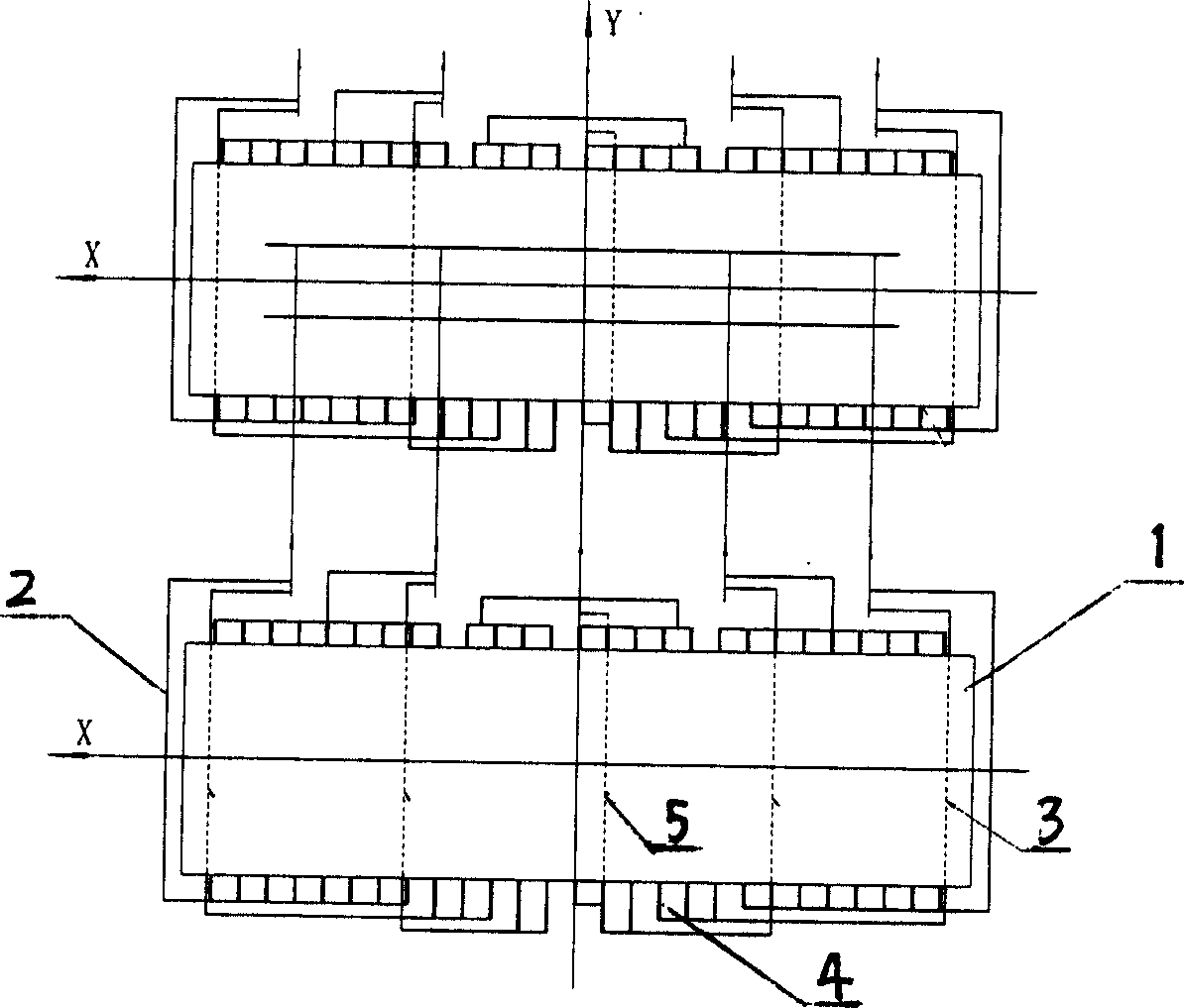
[0010] Embodiment of the present invention: 50% of the electric current of the electrolytic cell (1) flows out from 27 cathode soft busbars (4) on the power inlet side (the other 50% flows out from the cathode soft busbars on the power outlet side), and the electrolytic cell (1) longitudinal axis ( figure 1 Y-axis) as the center, the 3 slot bottom busbars (3) and the slot side busbars (2) near the flue end (right side) are connected 3 more than the 2 slot bottom busbars and the slot side busbars at the aluminum outlet (left side) One cathode soft busbar (4), so that the right busbar (3) at the bottom of the tank (3) flows into 3 more currents than the left side, and realizes the current asymmetrical configuration. The 3 bottom busbars (3) on the right are one more than the 2 busbars on the left, forming an asymmetric arrangement of the busbars at the bottom of the groove, and the first busbar (5) on the right side near the Y axis is arranged in At the first cathode flexible b...


PUM


Abstract

The invention discloses a dissymmetrical bottom generatrix and the current configuration method. The current from the cathode soft generatrix distributes in the electrode in the bottom generatrix and side generatrix centered on the Y axis. The current of bottom generatrix and the side generatrix near the flue (right) is higher than that of the aluminium-outputting terminal. The invention, owing to adopting the dissymmetrical configuration of bottom generatrix and the dissymmetrical configuration of the current, can effectively reduce the magnetic field produced by the electrobath, overcome the influence of the critical magnetic field of the slot, make the magnetic field reach the effects of cutting the peak and filling the flat, reduce the grads of the magnetic field and greatly increase the uniformity of the magnet.

Description

Technical field: [0001] The invention relates to a configuration method of busbars and current around a tank in the production of electrolytic aluminum. technical background: [0002] The cell capacity of modern prebaked anode electrolyzers is developing towards large-scale development, and the magnetic field of the electrolytic cell increases with the increase of cell capacity, and its influence is becoming more and more important. Due to the limitation of floor area and investment, the spacing between two (several) rows of electrolytic cells should not be too large. The increase of the vertical magnetic field caused by the small row spacing will cause the interface of the melt in the tank to be relatively large. Large fluctuations seriously interfere with the normal production of electrolyzers (especially large ones). Invention content: [0003] The purpose of the present invention is to provide an asymmetric tank bottom busbar and current configuration method, which ca...

Claims


Application Information

Patent Timeline
IPC IPC(8): C25C3/16H02G5/00
Inventor 杨朝红韩笑天颜非亚刘忠琼付长宏
Owner GUIYANG AL-MG DESIGN & RES INST
Why Eureka
Try Eureka