
Single crystal pulling device and method and superconducting magnet

Inactive Publication Date: 2006-01-10
KK TOSHIBA
View PDF4 Cites 7 Cited by
  • Summary
  • Abstract
  • Description
  • Claims
  • Application Information

AI Technical Summary

Benefits of technology

[0014]Another object of the present invention is to provide a superconducting magnet which can generate a uniform transverse magnetic field having a small magnetic-field gradient, particularly for the single-crystal pulling device.
[0032]According to the superconducting magnet of the present invention, a uniform transversal magnetic field having a small magnetic-field gradient can be generated inside the cylindrical vacuum vessel. In addition, the coaxial or square magnetic field distribution can be generated on the horizontal same plane, and an imbalanced electromagnetic force can be hence considerably suppressed.
[0033]Furthermore, according to a single-crystal pulling device of the present invention, which utilizes the superconducting magnet of the characters mentioned above, the uniform magnetic field region in a pulling direction is created, and a magnetic field in the direction of a transverse magnetic field is almost horizontal, and a high-quality single crystal can be manufactured by suppressing an imbalanced electromagnetic force.

Problems solved by technology

In the conventional configuration described above, because a magnetic field gradient in a bore (opening) range is excessively large as shown in FIG. 20, an effect of suppressing heat convection generated in the melt is unbalanced, and hence, magnetic field efficiency becomes poor.
For this reason, the suppressing accuracy of heat convection becomes poor, and it is hence difficult to pull up a single crystal having high quality.

Method used


Image

  • Single crystal pulling device and method and superconducting magnet
  • Single crystal pulling device and method and superconducting magnet
  • Single crystal pulling device and method and superconducting magnet

Examples


Embodiment Construction

[0050]Embodiment of the present invention will be described hereunder with reference to FIGS. 1 to 17.

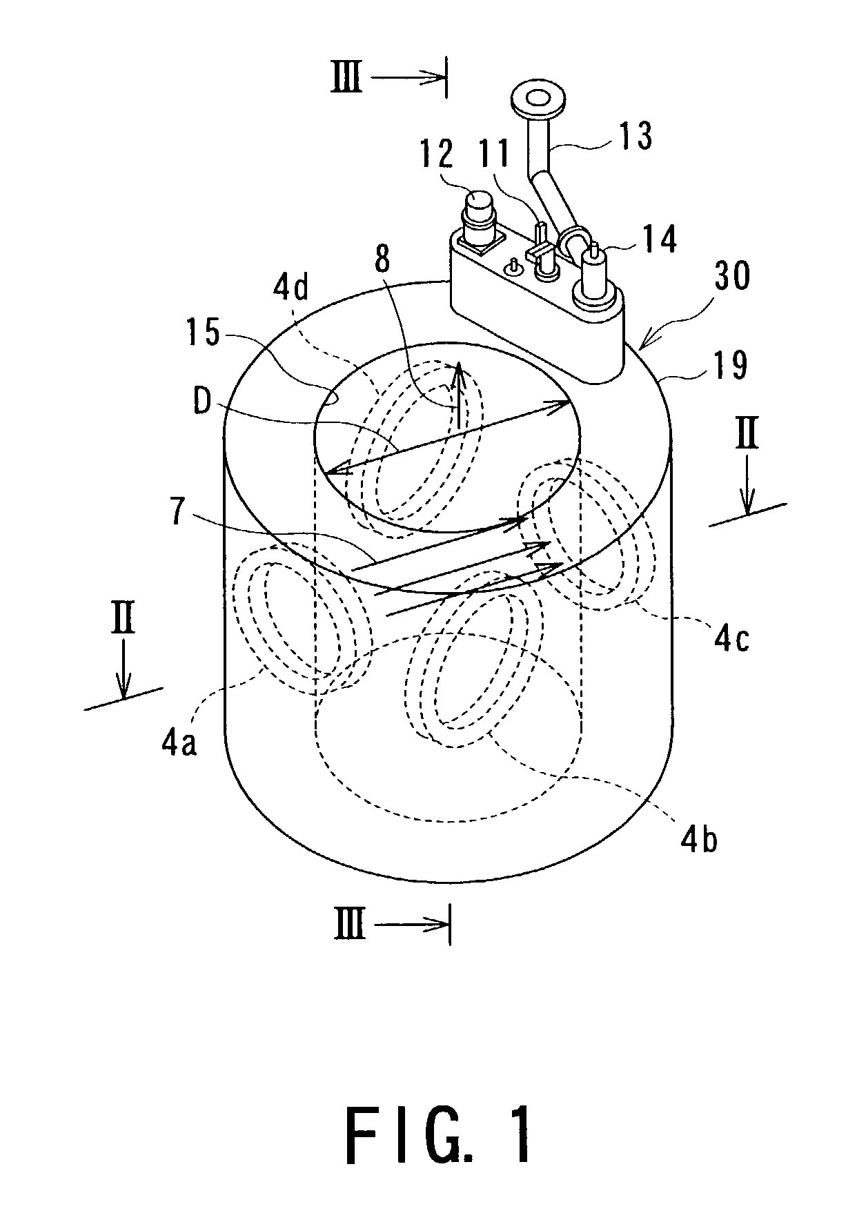
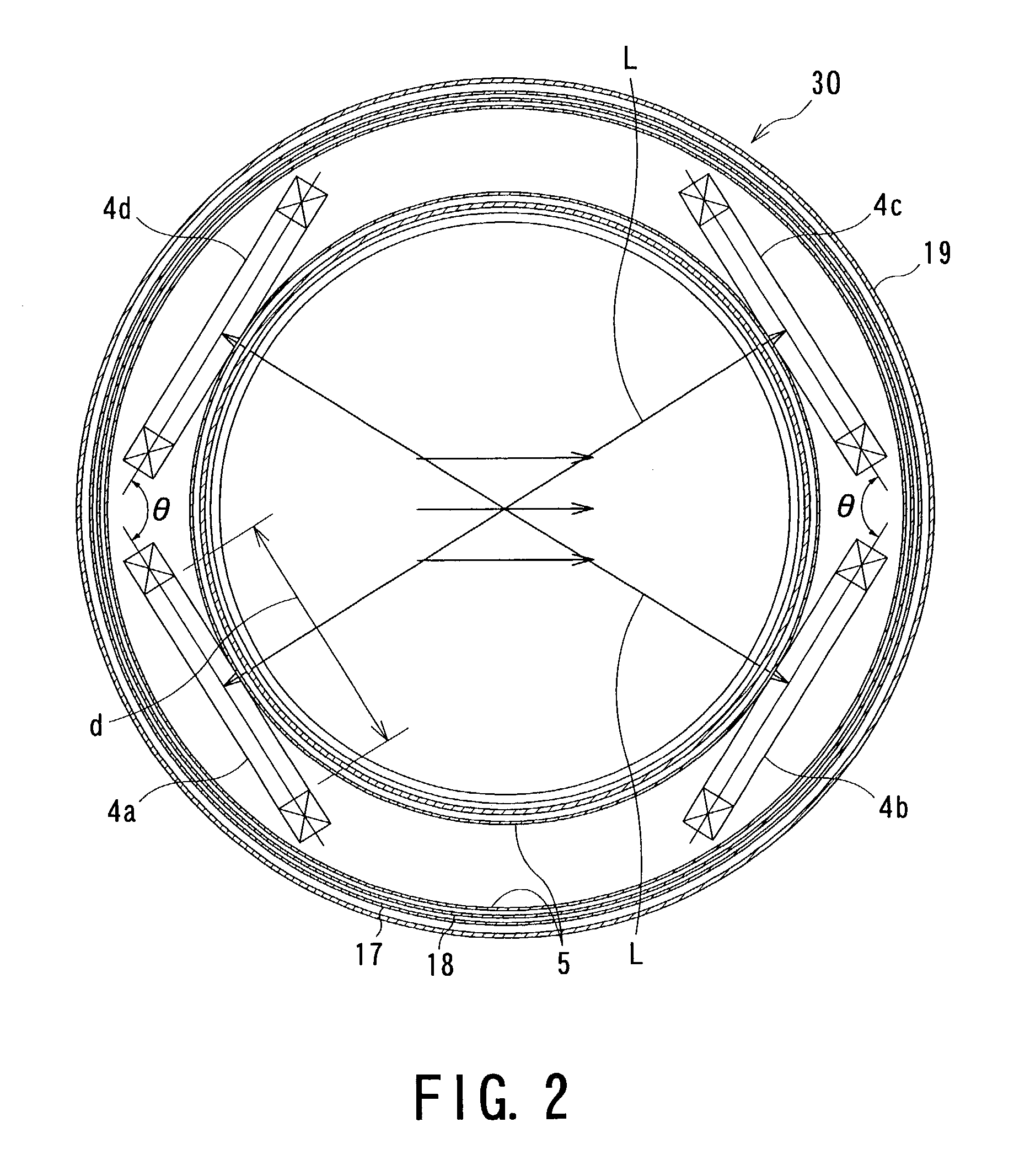
[0051]First, with reference to FIGS. 1 and 2, an entire superconducting magnet 30 of one embodiment of the present invention will be explained.

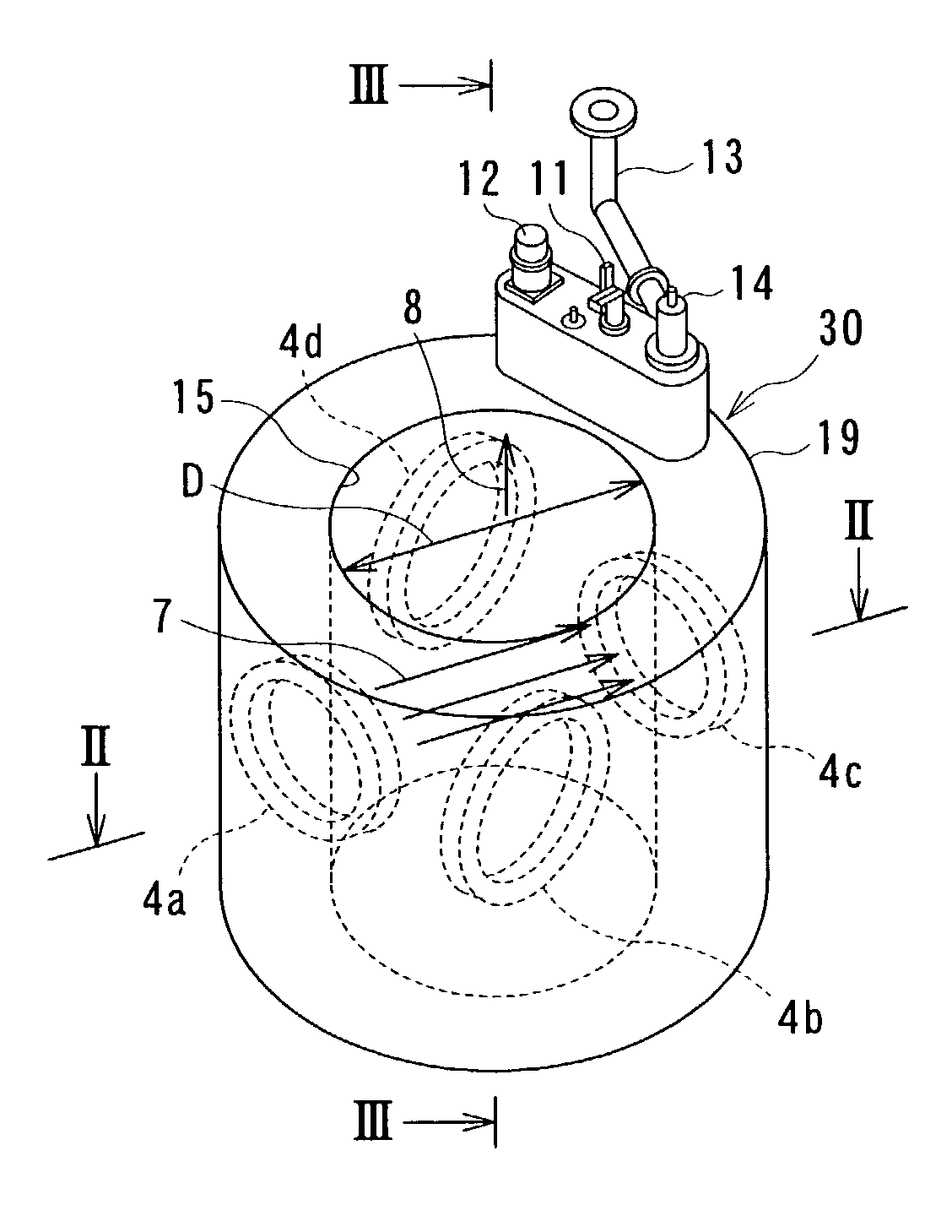
[0052]A cylindrical vessel 5 for coolant, cooling medium or refrigerant is arranged as a cooling vessel in a cylindrical vacuum vessel 19, which may be called hereinlater coolant vessel 5. Four superconducting coils 4a, 4b, 4c, and 4d are accommodated in the coolant vessel 5, and a current lead 11 for guiding a current is connected to the vacuum vessel 19. A small helium refrigerator 12 for cooling first and second radiation shields 17 and 18, a service port 14 having a filling port and a helium gas discharge port are also arranged to the vacuum vessel 19 in a state, for example, shown in FIG. 1.

[0053]In the described and shown embodiment, the superconducting coils 4a, 4b, 4c, and 4d are constituted as circular coils, arranged in the four qua...


PUM


Abstract

A single crystal pulling device is composed of a cylindrical pulling furnace, a crucible disposed in the pulling furnace in which a single crystal material for a semiconductor is poured, a cylindrical vacuum vessel coaxially disposed around the pulling furnace, and a superconducting magnet composed of a plurality pairs of coils arranged inside the vacuum vessel so as to generate magnetic field. The superconducting coils are arranged on the same horizontal plane of the cylindrical vacuum vessel, and each of the paired superconducting coils includes coils set so as to oppose to each other with respect to a central axis of the cylindrical vacuum vessel so that one coil of one pair of coils and one coil of another pair of coils adjacent to that one pair of coils constitutes a set angle, directing towards the inside of the cylindrical vessel, in a range of 100° to 130°.

Description

BACKGROUND OF THE INVENTION[0001]1. Field of the Invention[0002]The present invention relates to a single-crystal pulling device and a single-crystal pulling method used to manufacture a single crystal and a superconducting magnet applicable to the single-crystal pulling device.[0003]2. Related Art[0004]A semiconductor such as silicon or gallium arsenide consists of a single crystal, and is used for a memory device and the like of a computer having various sizes. It is therefore required for such memory device to be increased in its capacity, be produced at a reduced cost, and improved in its quality.[0005]In order to satisfy these requirements, prior art provides, as one single-crystal pulling method for manufacturing a single crystal, a method in which a magnetic field is applied to a semiconductor material set in a molten state and accommodated in a crucible. In this arrangement, heat convection generated in the melt is suppressed to manufacture a semiconductor having a large dia...

Claims


Application Information

Patent Timeline
IPC IPC(8): C30B15/20C30B15/00C30B15/30C30B29/06C30B30/04H01F6/00
CPCC30B15/305H01F6/00Y10T117/1052Y10T117/1004Y10T117/1072Y10S117/917
Inventor SHIMONOSONO, TSUTOMUKOGUCHI, YOSHIHIROSASAKI, TAKASHI
Owner KK TOSHIBA
Learn More