Acoustic fluid machine

a fluid machine and acoustic technology, applied in the direction of machines/engines, instruments, sound producing devices, etc., can solve the problems of high cost, complex structure, and inability to obtain the desired discharge pressur

Inactive Publication Date: 2006-03-16
ANEST IWATA CORP
View PDF10 Cites 7 Cited by
  • Summary
  • Abstract
  • Description
  • Claims
  • Application Information

AI Technical Summary

Benefits of technology

[0007] In view of the foregoing disadvantages, it is an object of the present invention to provide an acoustic fluid machine in which temperature gradient between the base and the top end of an acoustic resonator is kept as small as possible.

Problems solved by technology

Should resonation frequency be out of the predetermined range, compression ratio becomes smaller, making it impossible to obtain a desired discharge pressure.
Accordingly, it is necessary to use arithmetic equipment to control the actuator of the piston, which makes its structure complicate and involves high cost.

Method used


Image

  • Acoustic fluid machine
  • Acoustic fluid machine
  • Acoustic fluid machine

Examples


Embodiment Construction

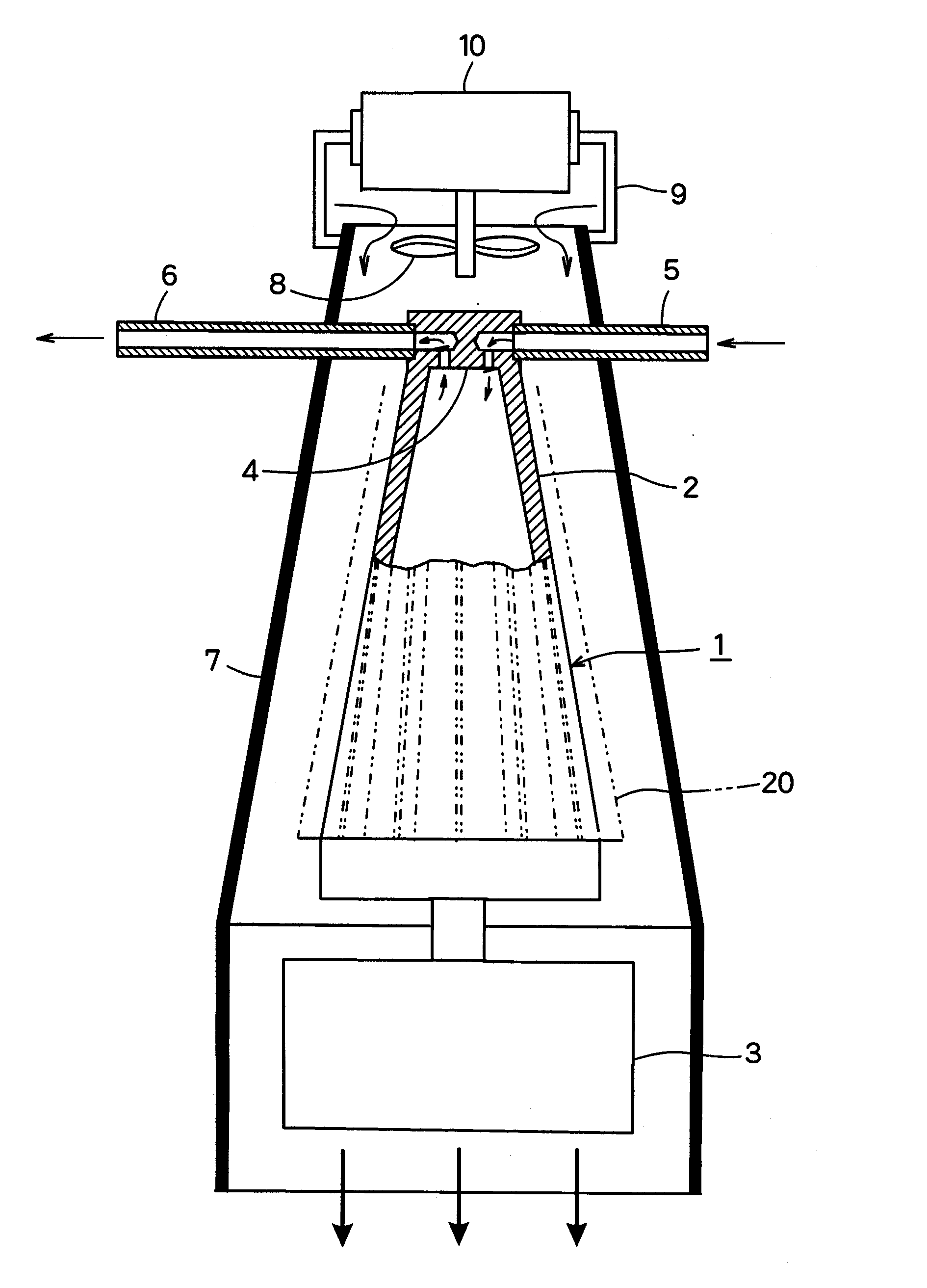
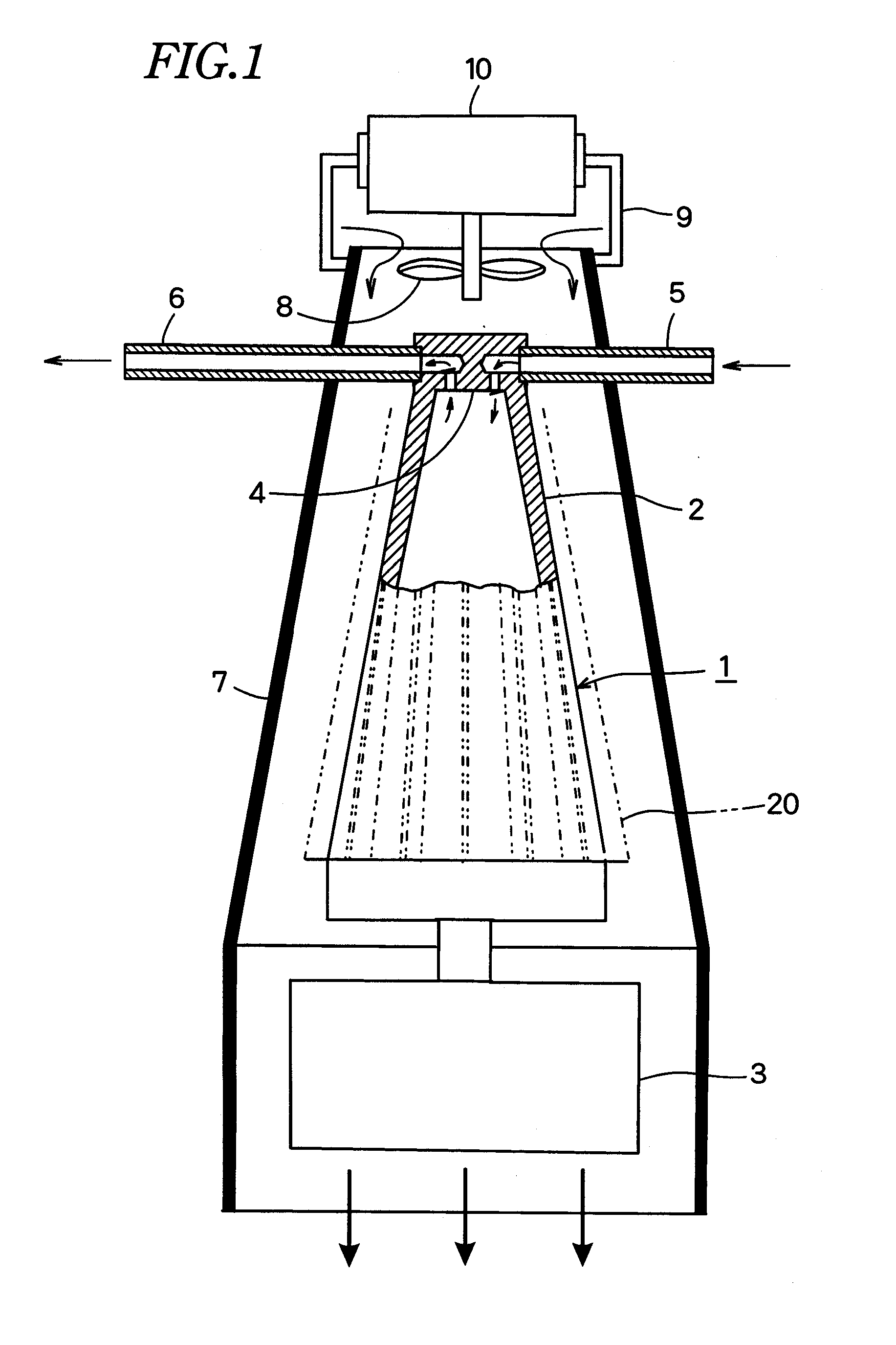
[0016] Numeral 1 denotes an acoustic fluid machine in which an acoustic resonator 2 has an actuator 3 in a larger-diameter base. A piston (not shown) is reciprocated axially at high speed at very small amplitude. Owing to pressure fluctuation in the acoustic resonator 2 involved by reciprocal motion of the piston, air and other fluid are sucked into the acoustic resonator 2 through a sucking pipe 5 and discharged from a discharge pipe 6.

[0017] The acoustic fluid machine 1 is contained with a space in a gas guide 7 that opens at the top end and the base end. A fan 8 is provided inside the top end of the gas guide 7.

[0018]FIG. 1 shows that the fan 8 is driven by an electric motor 10 mounted to the outer surface of the top end of the gas guide 7 by a bracket 9.

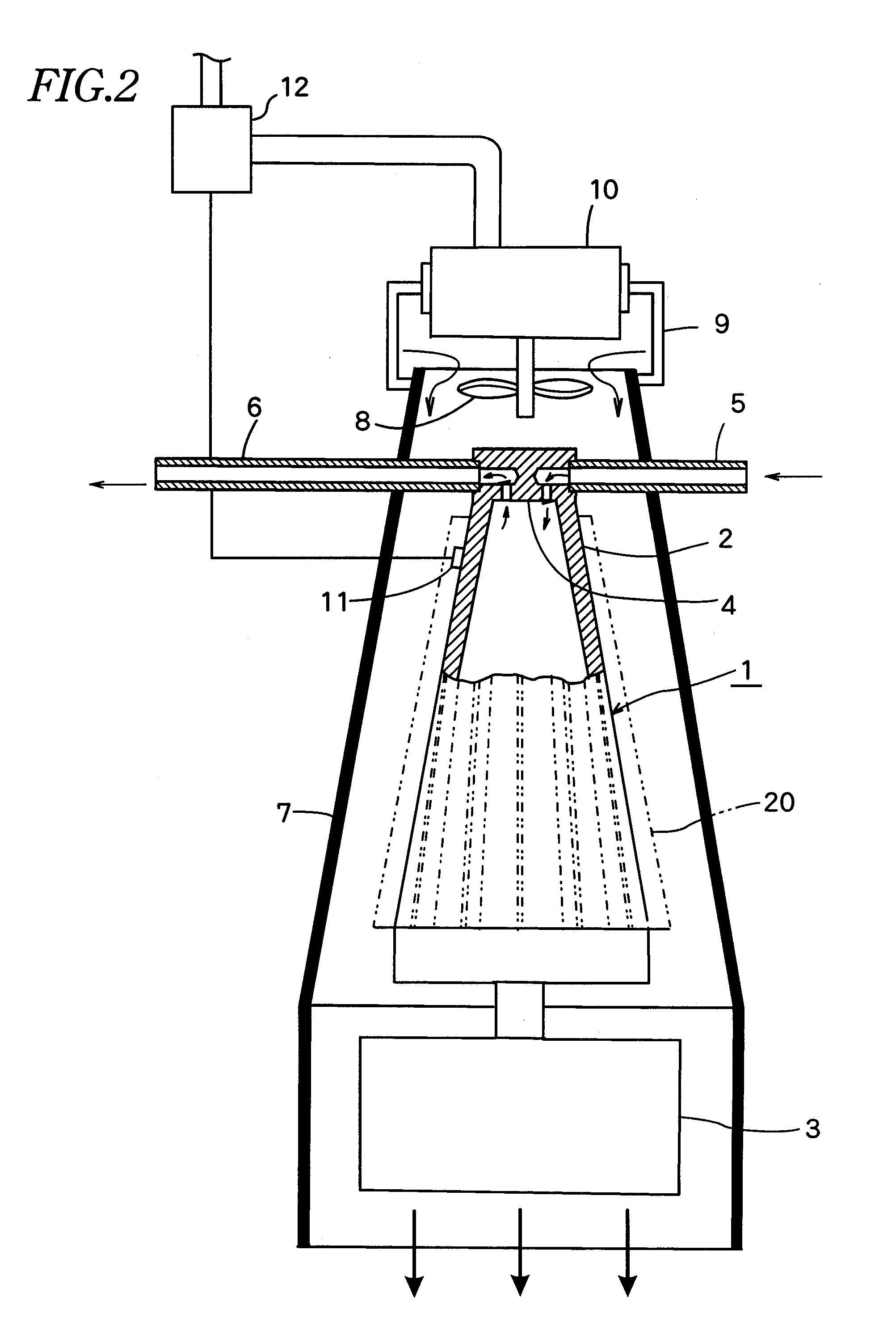
[0019]FIG. 2 shows that a control unit 12 allows electricity supplied into the electric motor 10 in FIG. 1 to vary depending on detected temperature of a temperature sensor 11 in the acoustic resonator 2. Thus, the quantity of...


PUM


Abstract

In an acoustic resonator, an actuator allows a piston to reciprocate axially at very small amplitude at high speed. Owing to pressure fluctuation in the acoustic resonator involved by reciprocal motion of the piston, fluid is sucked into and discharged from the acoustic resonator via a valve device at the top end of the acoustic resonator. The acoustic resonator is covered with a gas guide with a space. The valve device is cooled by a fan at the top end of the gas guide.

Description

BACKGROUND OF THE INVENTION [0001] The present invention relates to an acoustic fluid machine to keep temperature gradient as small as possible between the base having an actuator for an acoustic resonator and the top end having a valve device for sucking and discharge. [0002] Japanese Patent Pub. No. 2004-116309A corresponding to U.S. patent application Ser. No. 10 / 922,383 filed Aug. 19, 2004 discloses an acoustic fluid machine in which an actuator that has a piston is provided at the base of a tapered acoustic resonator for creating in-tube wave motion with acoustic resonation, and a valve device for sucking and discharging fluid with pressure fluctuation therein. [0003] In the acoustic fluid machine, only when fluid temperature is within a certain range, the shape and size of the acoustic resonator enables the optimum resonation frequency to be produced, thereby carrying out the optimum sucking and discharge of the fluid. Should resonation frequency be out of the predetermined ra...

Claims


Application Information

Patent Timeline
Patent Type & Authority Applications(United States)
IPC IPC(8): F01N1/14
CPCF04F7/00G10K11/22G10K11/02
Inventor KAWAHASHI, MASAAKIFUJIOKA, TAMOTSUHOSSAIN, MOHAMMED ANWARSAITO, MASAYUKI
Owner ANEST IWATA CORP
Why Eureka
Try Eureka